Polygonal Medallion

Class-1 -- Floral Medallion --

In this class , we make three floral medallions using the papers provided. The final results and the diagrams used are shown below.
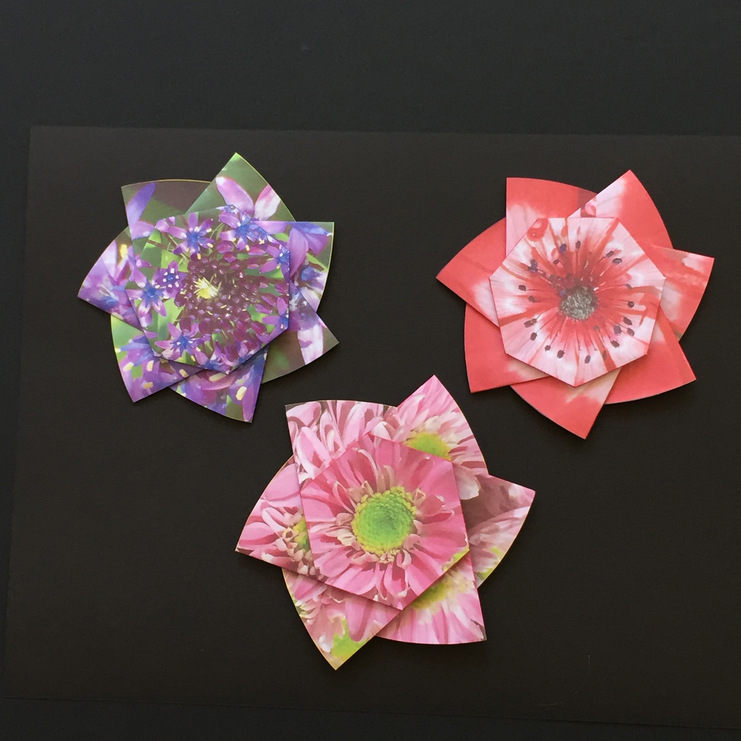
     Fig.1-1 Final appearance
         click to enlarge & print
18_class1.jpg

Basic Twist Diagram

The diagrams are created by inserting the following twist fold pattern drawings on top of the flower images.
Notice that the paper to be used has a circular boundary.
    Fig. 1-2A   Hexagon Twist Diagram
         click here to enlarge
i
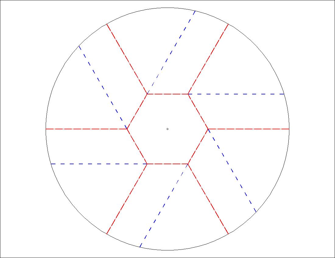
    Fig. 1-2B   Heptagon Twist Diagram
         click here to enlarge
i

Flower image and its corresponding folding diagram

( 1 ) Example of a cluster of flowers

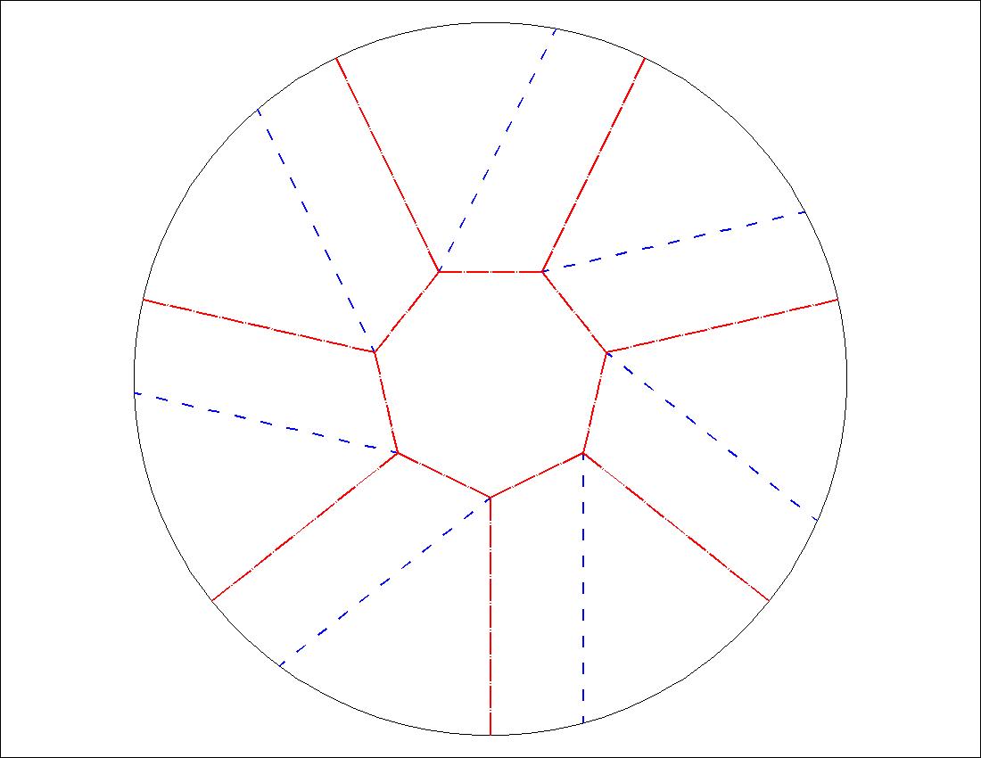
    Fig. 1-3A   Model 1 Flower image
         click here to enlarge
i
    Fig. 1-3B   Model 1 Diagram
         click here to enlarge
i


( 2 ) Example of a single flower1

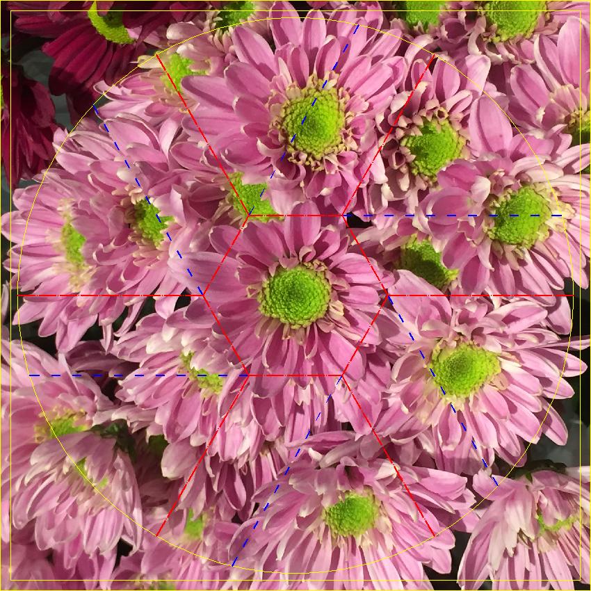
    Fig. 1-4A   Model 2 Flower image
         click here to enlarge
i
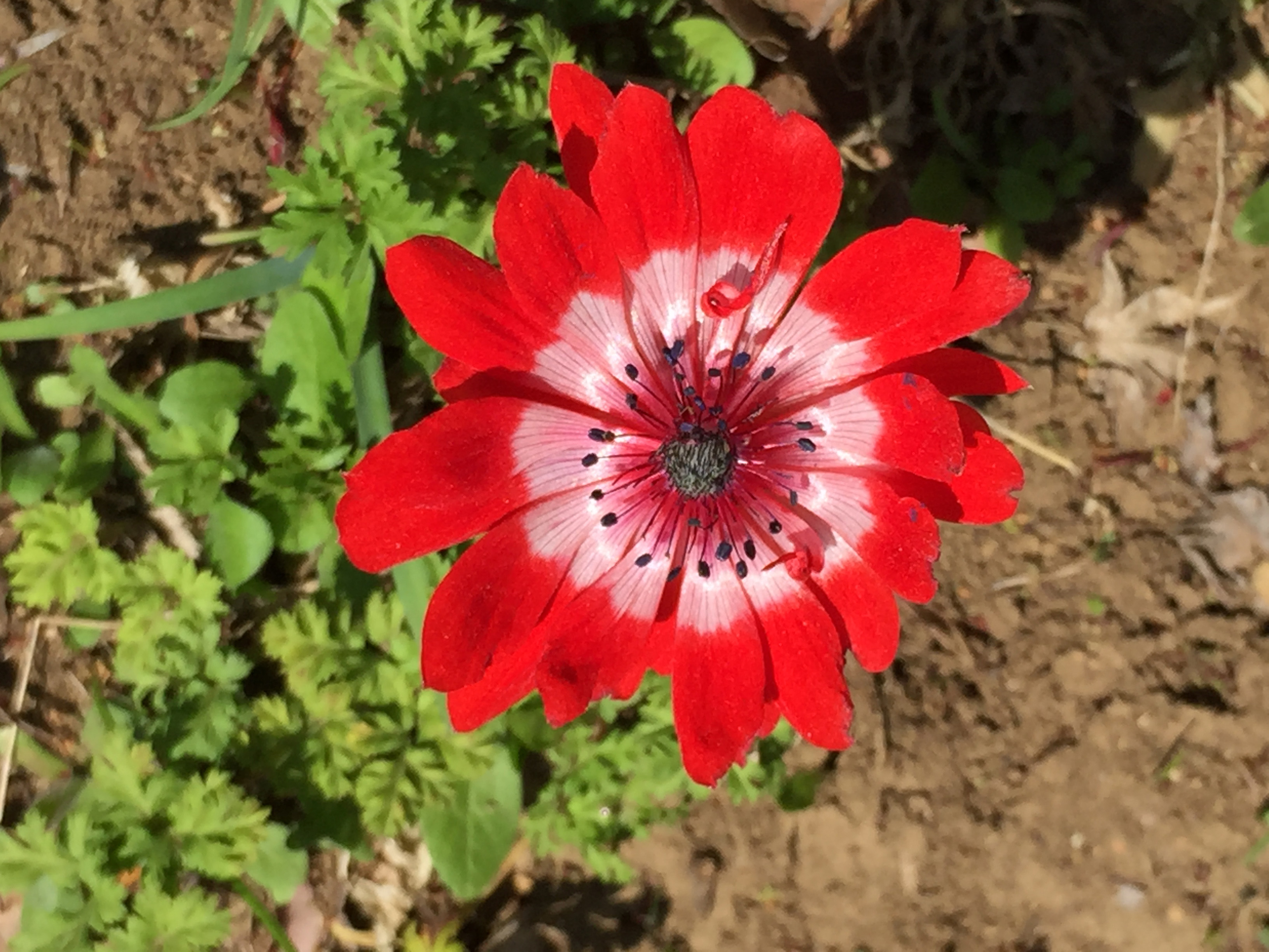
    Fig. 1-4B   Model 2 Diagram
         click here to enlarge
i

(3) Example of a single flower2

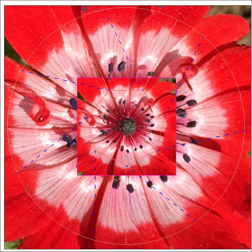
    Fig. 1-5A   Model 3 Flower image
         click here to enlarge
i
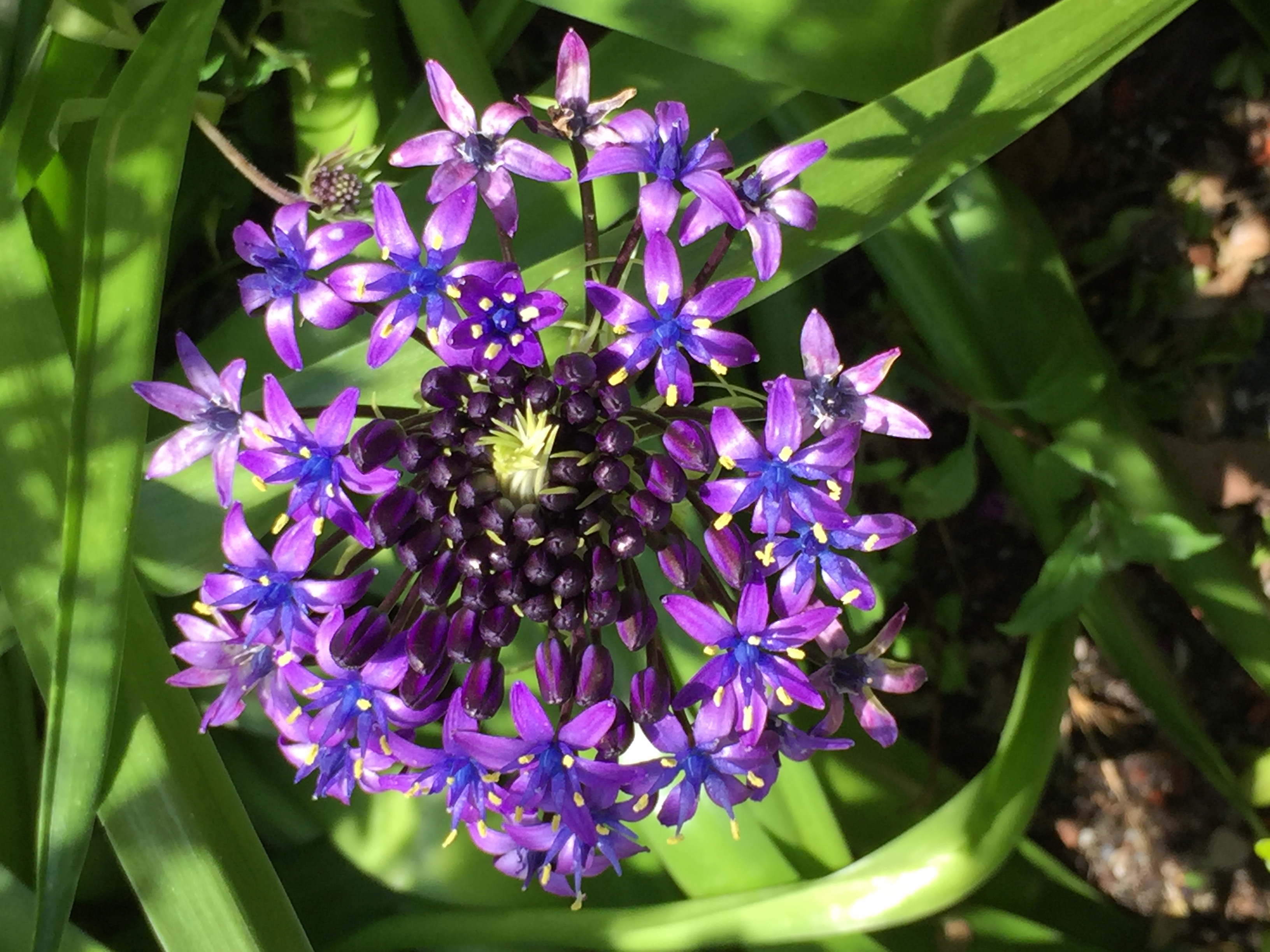
     Fig. 1-5B  Model 3 Diagram
         click here to enlarge
i

Class - 2 -- Polygonal Medallion -Spirals --

In this class , we make two spiral medallions ,pentagon and hexagon , as shown below.
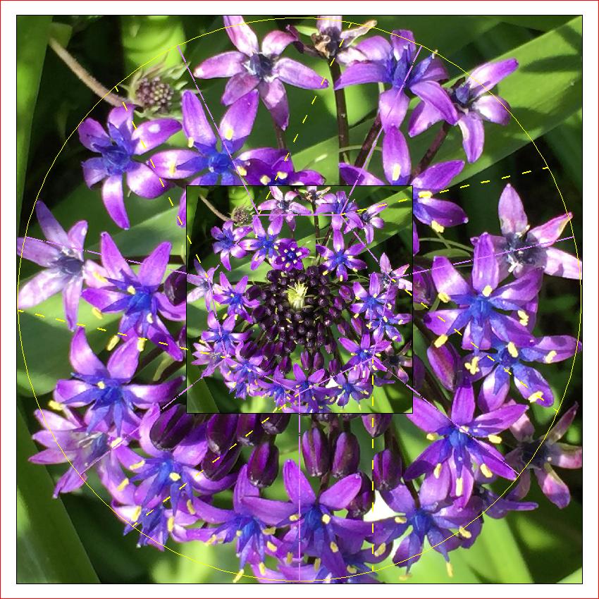
      Fig. 2-1A  Pentagonal Spiral
         click to enlarge & print
pent_twst_final.jpg
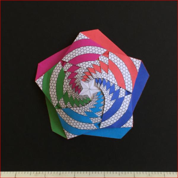
      Fig. 2-1B  Hexagonal Spiral
         click to enlarge & print
hex_twst_final.jpg

Pentagon spiral Model Pattern

The pentagonal spiral is made up of the multiple pieces shown below.
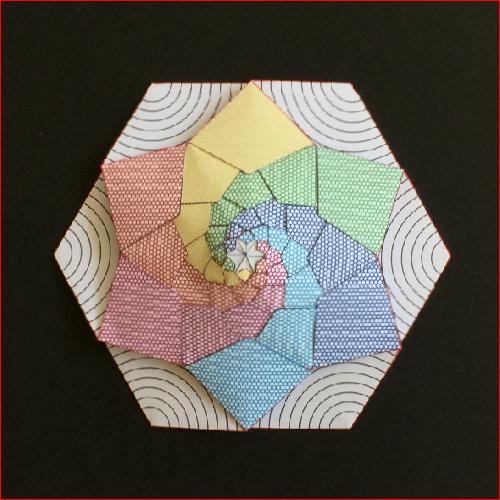
    Fig. 2-2   Pentagonal spiral components
         click here to enlarge
i

The final bare minimum folding diagram and its dimensions are shown in the following figures.
In the figure with dimensions, there are two center circles. Outer circle is the circle for the pentagon
resulted from folding , and the inner one is for the inscribing pentagon . The ratio is the reduction
scale factor. The ratio is 0.8416 (1.683 / 2.0) for the pentagon case. Then applying this ratio
repeatedly, we will have folding diagrams with constant reduction factor.

Pentagon Basic Pattern & Dimension

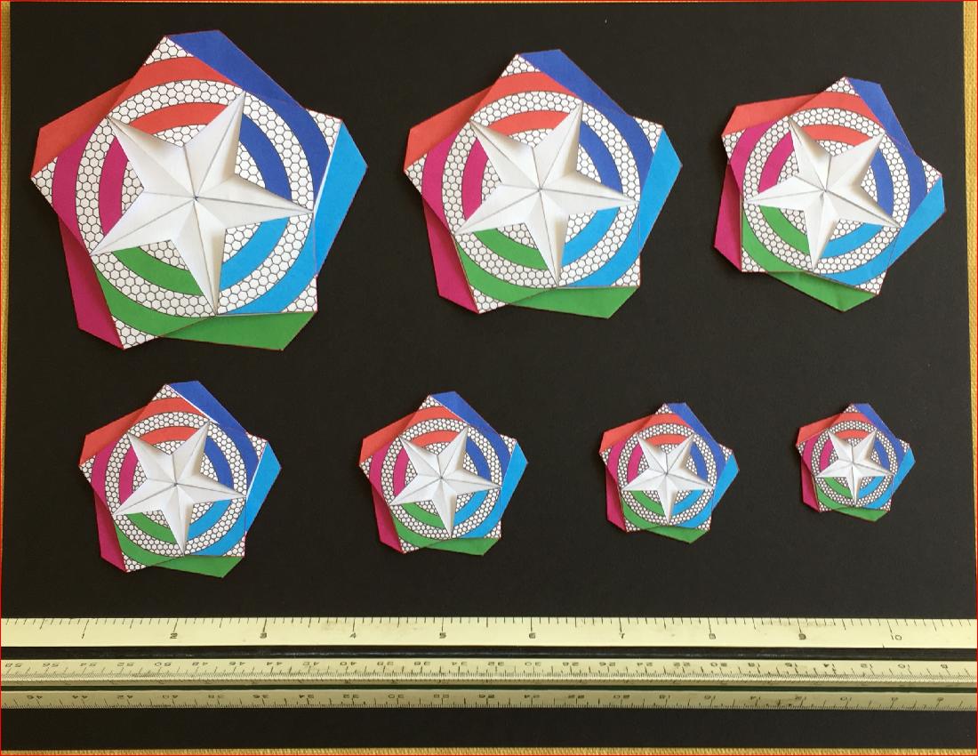
   Fig. 2-3A  Pentagon Basic Pattern
         click to enlarge & print
pent_base.jpg
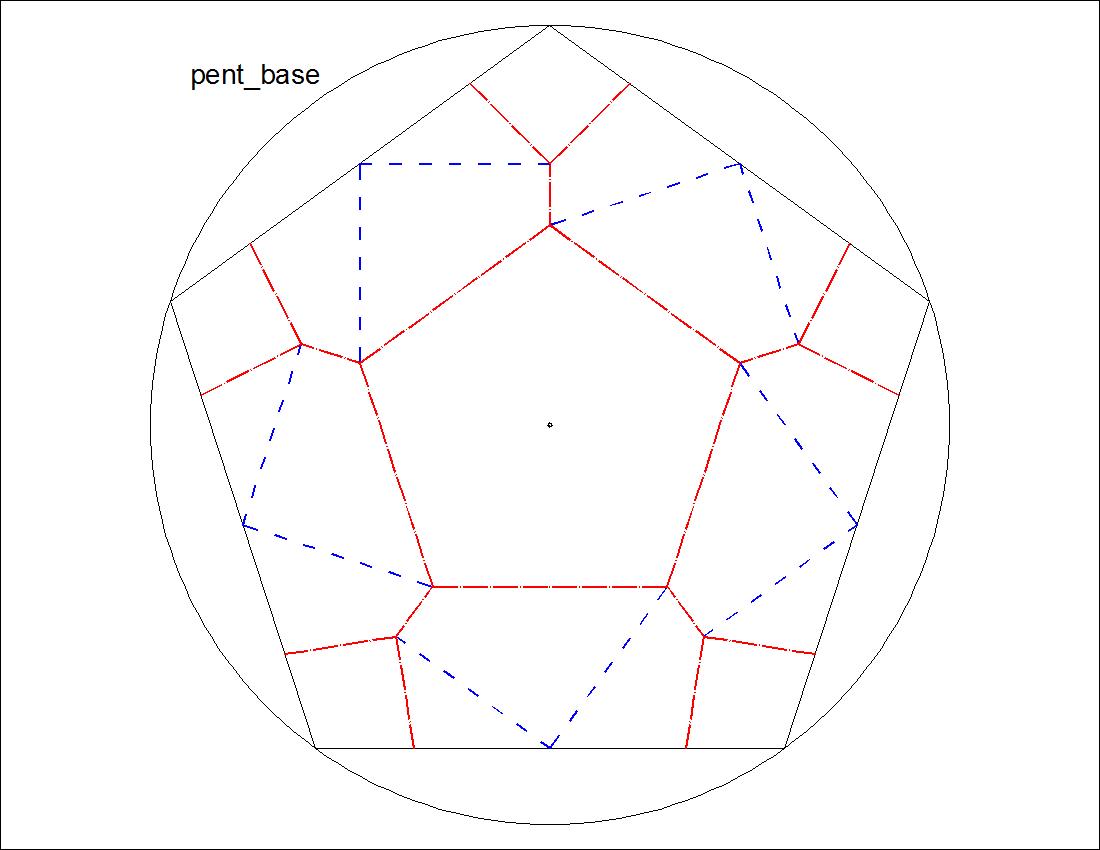
Fig. 2-3B  Pentagon Basic Pattern Dimension
         click to enlarge & print
pent_base_dim.jpg
The diagrams are as follows:
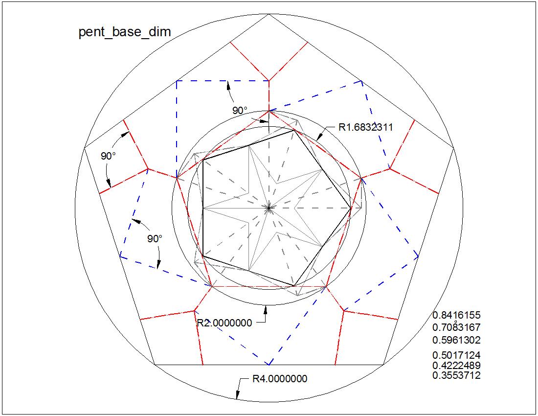
    Fig. 2-4A   Pentagon pattern-00
         click here to enlarge
i
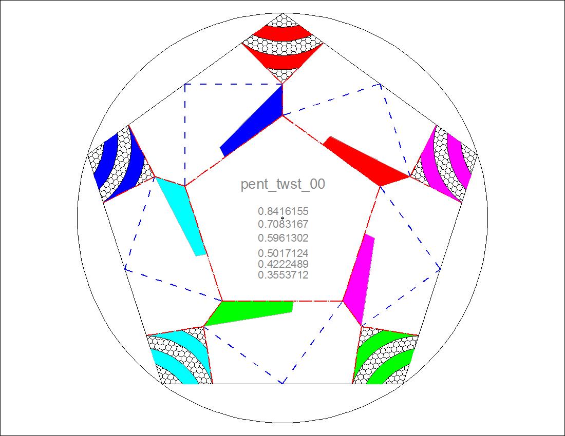
     Fig. 2-4B  Pentagon pattern-16
         click here to enlarge
i
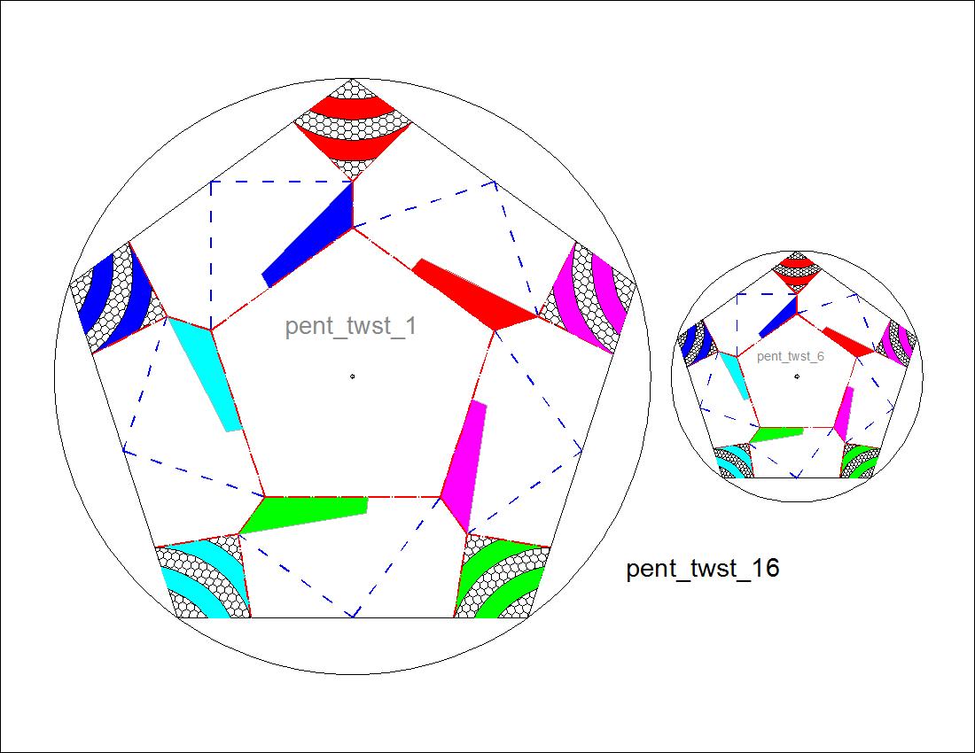
    Fig. 2-4C   Pentagon pattern-25
         click here to enlarge
i
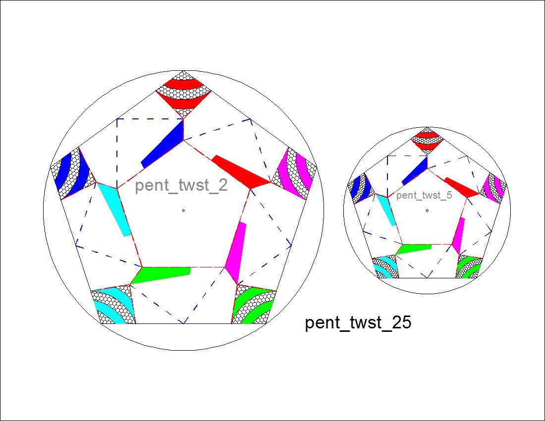
     Fig. 2-4D  Pentagon pattern-34
         click here to enlarge
i

Hexagon Spiral Model Pattern

The hexagonal spiral is made up of the multiple pieces shown below.
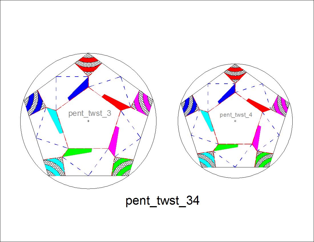
    Fig. 2-5   Hexagonal spiral components
         click here to enlarge
i

The final bare minimum folding diagram and its dimensions are shown in the following figures. In the figure with dimensions, there are two center circles. Outer circle is the circle for the hexagon resulted from folding , and the inner one is for the inscribing hexagon . The ratio is the reduction scale factor. The ratio is 0.73205 (1.464 / 2.0) for the hexgon case. Then applying this ratio repeatedly , we will have folding diagrams with constant reduction factor.
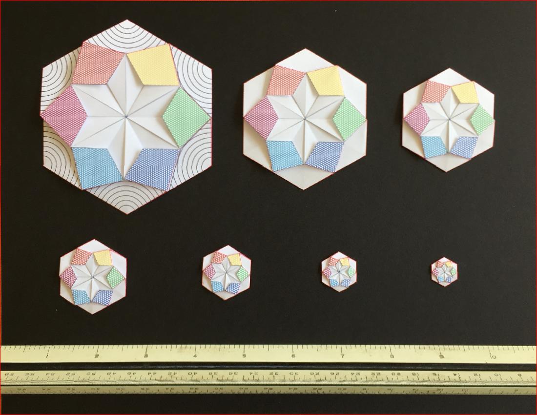
      Fig. 2-6A  Hexagon Twist Base
         click to enlarge & print
hex_base.jpg
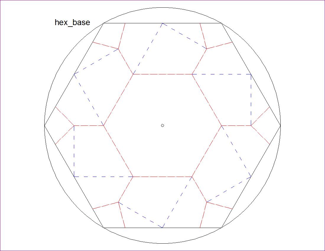
      Fig. 2-6B  Hexagon Twist Basic Dimension
         click to enlarge & print
hex_base_dim.jpg
The diagrams are as follows:
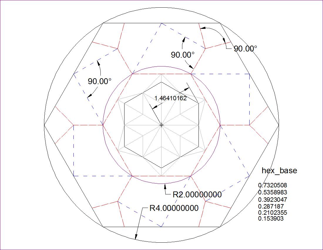
  Fig. 2-7A   Hexagon Pattern-00
         click here to enlarge
i
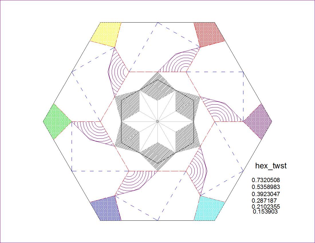
   Fig. 2-7B  Hexagon Pattern-12
         click here to enlarge
i
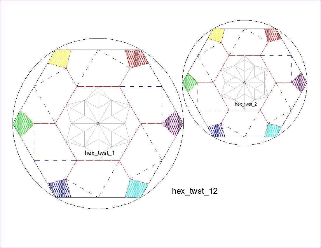
  Fig. 2-7C   Hexagon Pattern-3456
         click here to enlarge
i

Class - 3 -- CAD Usage for Twist Fold --

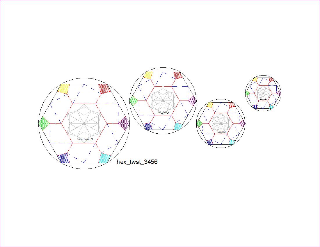
       Fig. 3-1A Model (I)
         click to enlarge & print
i
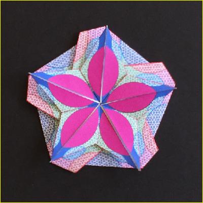
       Fig. 3-1B Model (II)
         click to enlarge & print
i

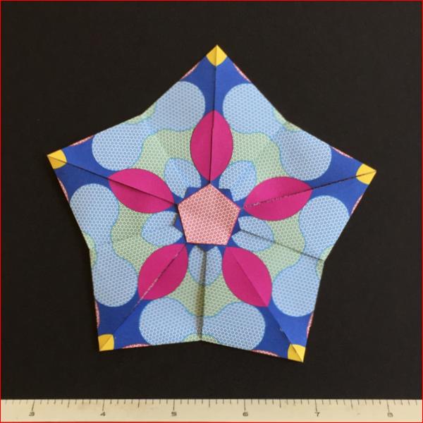
  There are 2 basic ways to accomplish "Twist Fold" though there are many variations based on them.
 Here, as an exmple, a regular pentagon is chosen for the purpose of discussion, but the same idea
  can be applied to any "N"-gons.  Two pentagons, outer and inner, are arranged so that the line connecting the center point
  and each apex of the inner pentagon passes through ,either the apex of the outer pentagon (Type-II) or
  the mid-point of the outer pentagon's side (Type-I).
 We also observe that in both cases angles are divided into 4 equal parts, at each mid-point of the side (Type-I)
 or at each apex (Type-II).
 So the each angle is
   Type-I       180/4 = 45 degrees
   Type-II      108/4 = 27 degrees
  Typical diagrams and their dimensions are shown in the following figures.
      Fig.3-2A  Type-I Dimension
         click to enlarge & print
mod1_dim.jpg
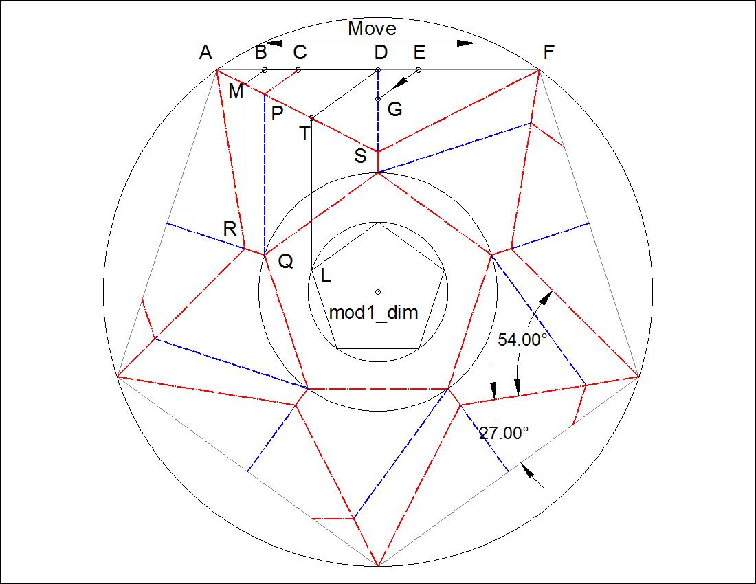
      Fig. 3-2B  Type-II Dimension
         click to enlarge & print
mod2_dim.jpg

Using the dimensional drawing above, it is possible to create folding diagrams for multiple values of radii
of circles circumscribing the inner pentagons. The results are shown below.

Type-I Twist

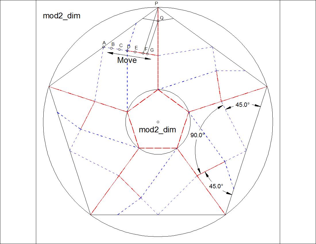
      Fig. 3-3A  Type-I Group-Front Face
         click to enlarge & print
mod1_front.jpg
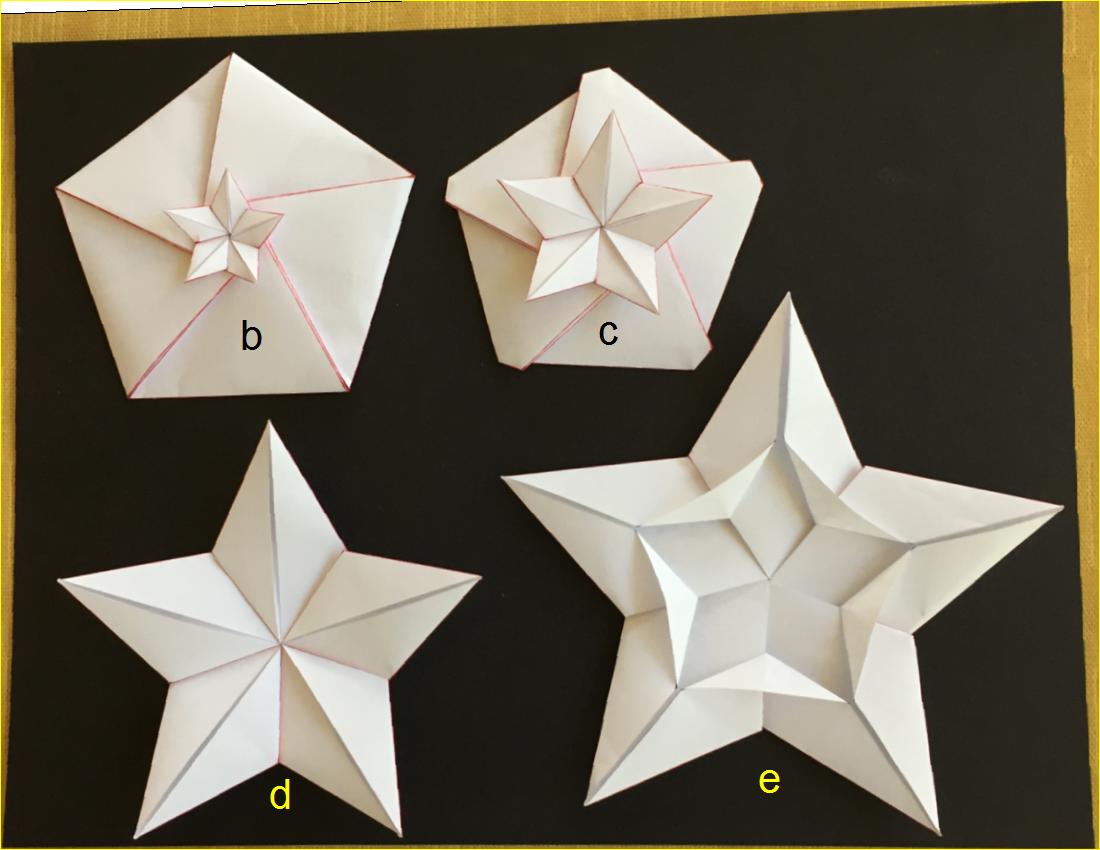
      Fig. 3-3B  Type-I Group-Back Face
         click to enlarge & print
mod1_back.jpg

Diagrams for Type-I Group

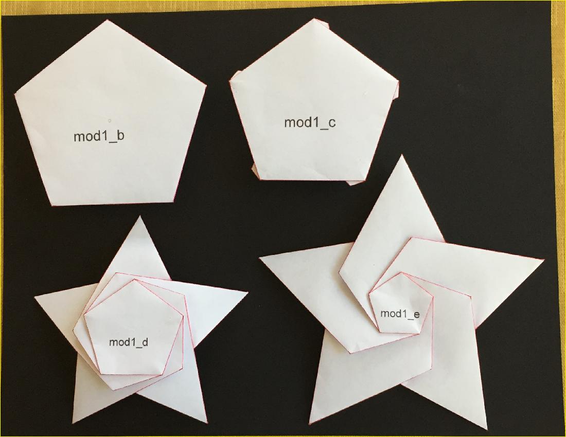
      Fig. 3-4A  Type-I "B" diagram
         click to enlarge & print
mod1_b.jpg
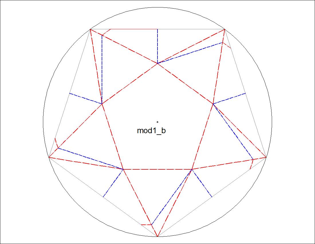
      Fig. 3-4B  Type-I "C" diagram
         click to enlarge & print
mod1_c.jpg
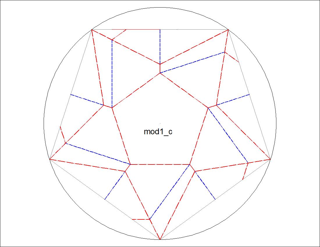
      Fig. 3-4C  Type-I "D" diagram
         click to enlarge & print
mod1_d.jpg
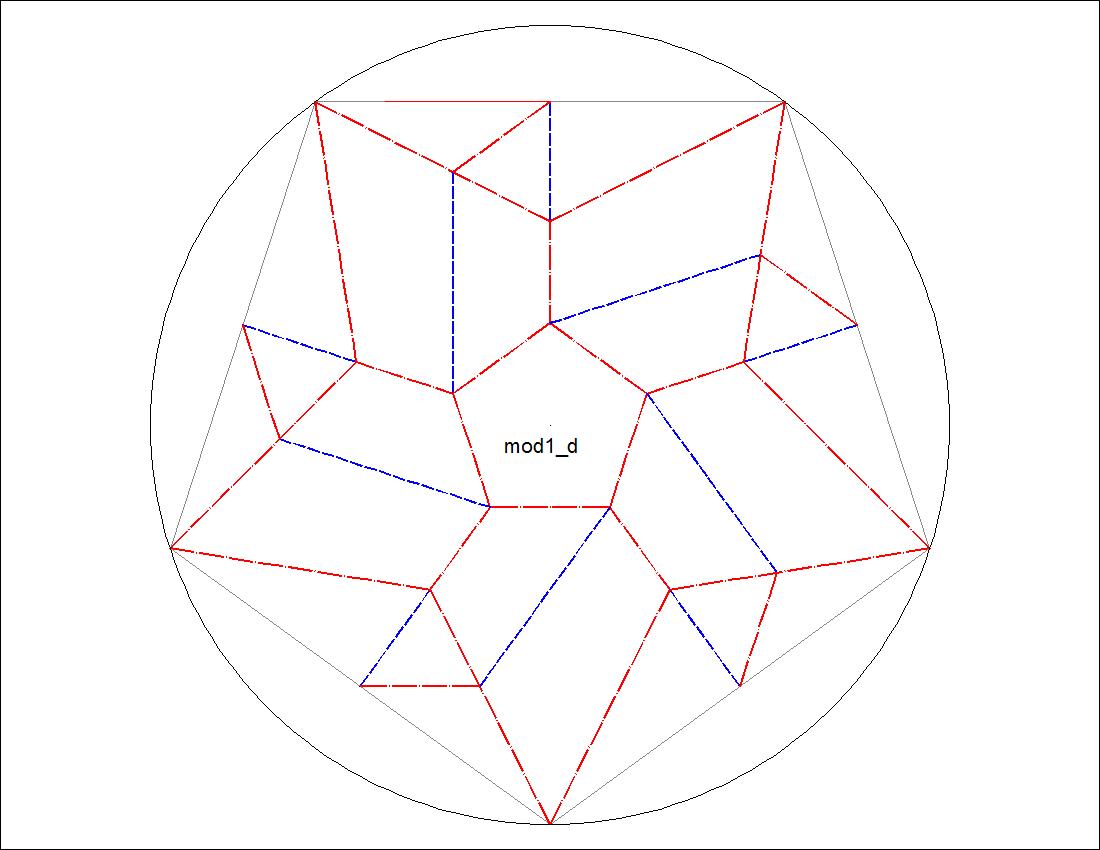
      Fig. 3-4D  Type-I "E" diagram
         click to enlarge & print
mod1_e.jpg

Type-II Twist

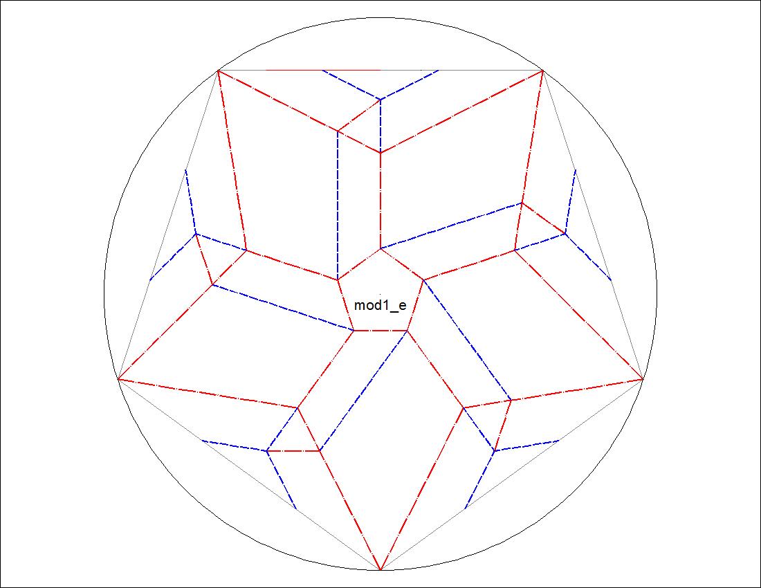
      Fig. 3-5A  Type-II Group-Front Face
         click to enlarge & print
mod2_front.jpg
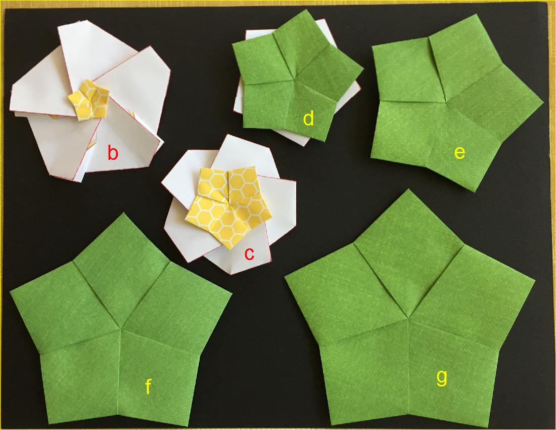
      Fig. 3-5B  Type-II Group-Back Face
         click to enlarge & print
mod2_back.jpg

Diagrams for Type-II Group

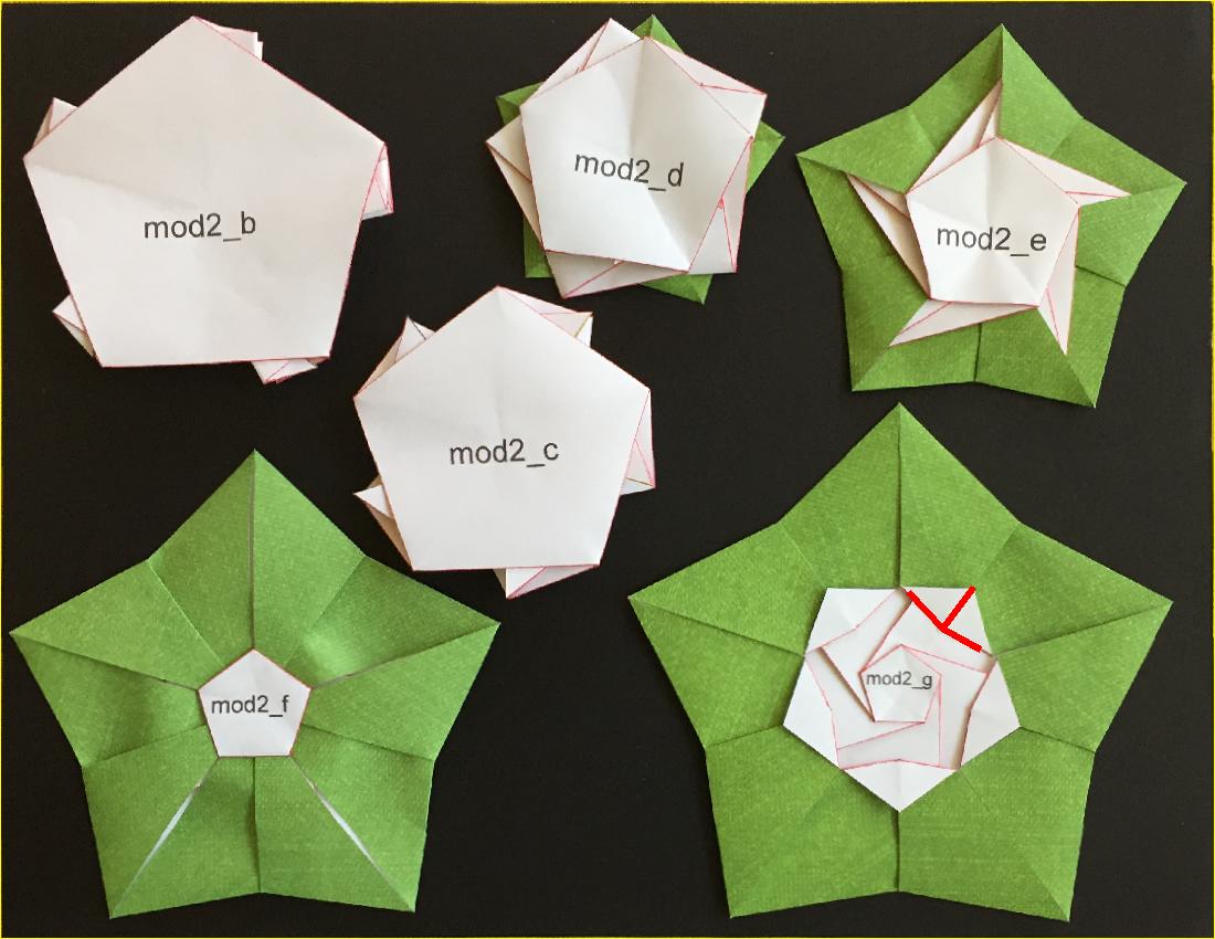
      Fig. 3-6A  Type-II "B" diagram
         click to enlarge & print
mod2_b.jpg
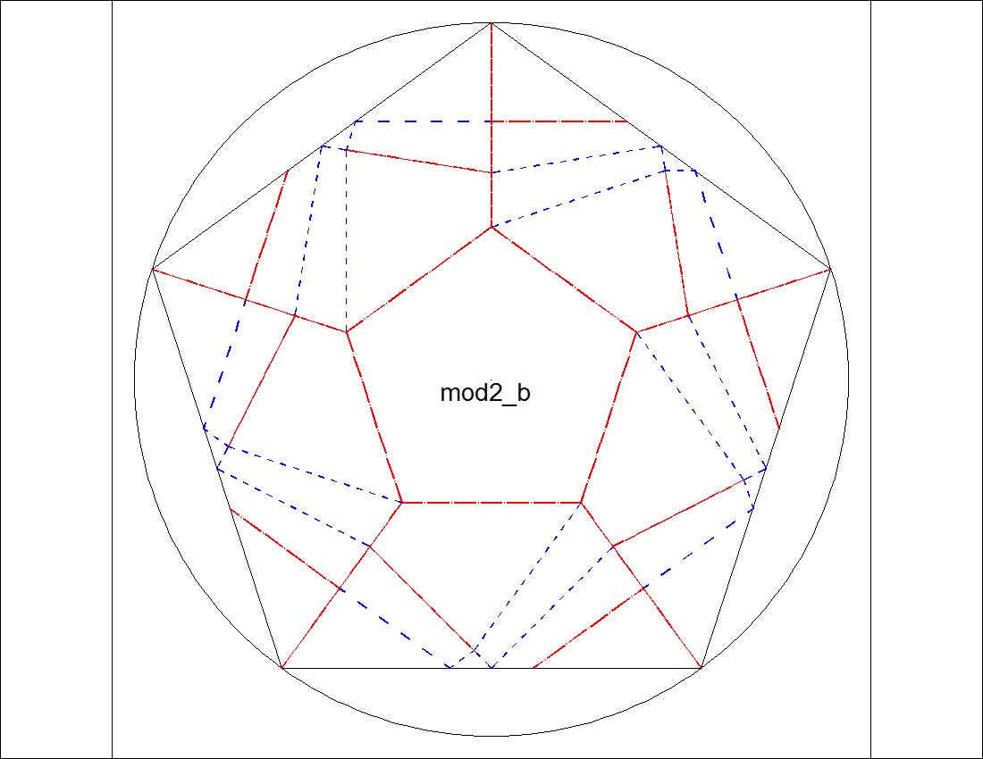
      Fig. 3-6B  Type-II "C" diagram
         click to enlarge & print
mod2_c.jpg
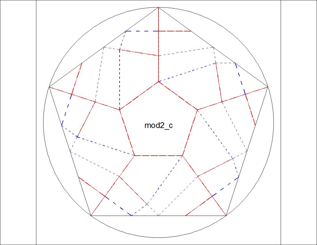
      Fig. 3-6C  Type-II "D" diagram
         click to enlarge & print
mod2_d.jpg
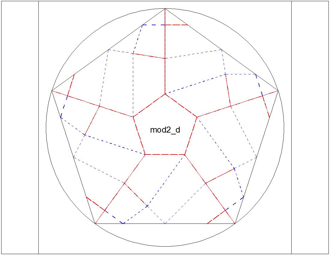
      Fig. 3-6D  Type-II "E" diagram
         click to enlarge & print
mod2_e.jpg
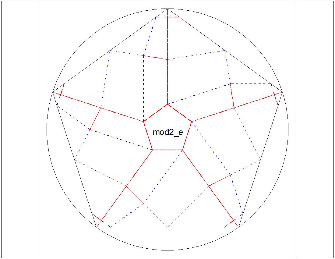
      Fig. 3-6E  Type-II "F" diagram
         click to enlarge & print
mod2_f.jpg
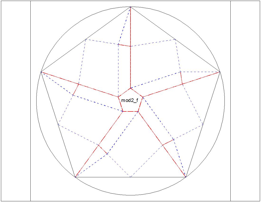
      Fig. 3-6F  Type-II "G" diagram
         click to enlarge & print
mod2_g.jpg
  

Observing these 2 figures,we notice that
1. In Type -I, somewhere between "C" and "D" ,the radii of the base pentagon and five-pointed-star become identical.
2. In Type - II, between "F" and "G", the red colored tip will be partially hidden under the center pentagon.
How can we find the exact location ?

Model - I

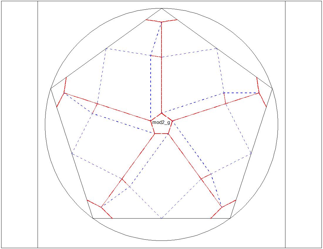
      Fig. 3-7A  Dimension for "B" & "D"
         click to enlarge & print
mod1_b+d.jpg
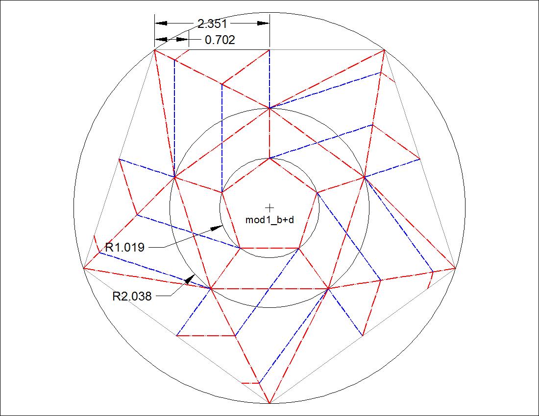
      Fig. 3-7B  Parameter Graph
         click to enlarge & print
pent_inside_54_para.jpg

The diagrams for case "B" and "D" are drawn on the same drawing.
In the drawing, "B" "D"
radius of the Star : 0.702 2.351
radius of the base pentagon : 2.038 1.019
This set of data are plotted as a graph , Star Radius ( red ) and Base Radius ( blue ).
Two lines intersects at radius = 1.527, this is the radius of the diagram to be used.
A new diagram is created and this is pasted over the separately prepared image file.
Both are shown in the figures below.
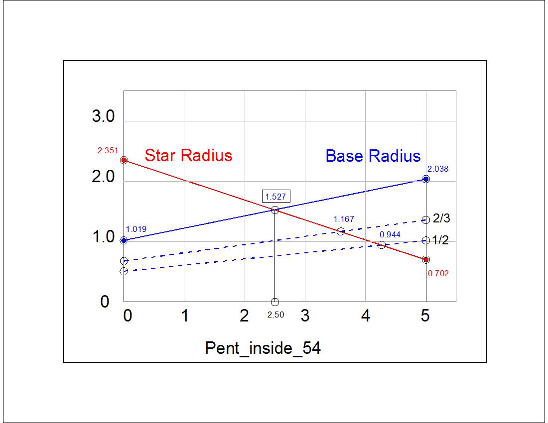
      Fig. 3-8A  Model-I base diagram
         click to enlarge & print
class_3_a_1.0.jpg
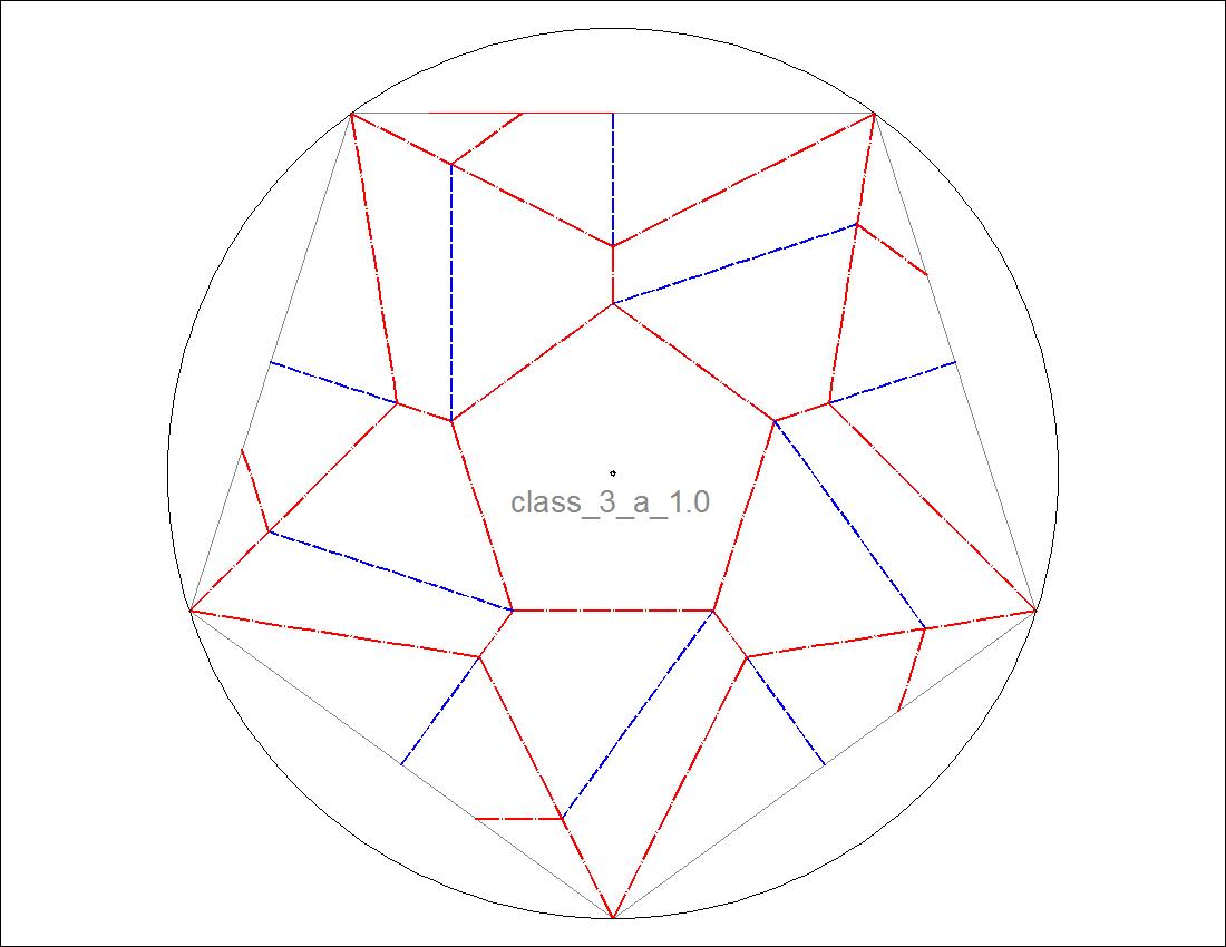
      Fig. 3-8B  Model-I Diagram
         click to enlarge & print
class3_ex1b.jpg

Model - II

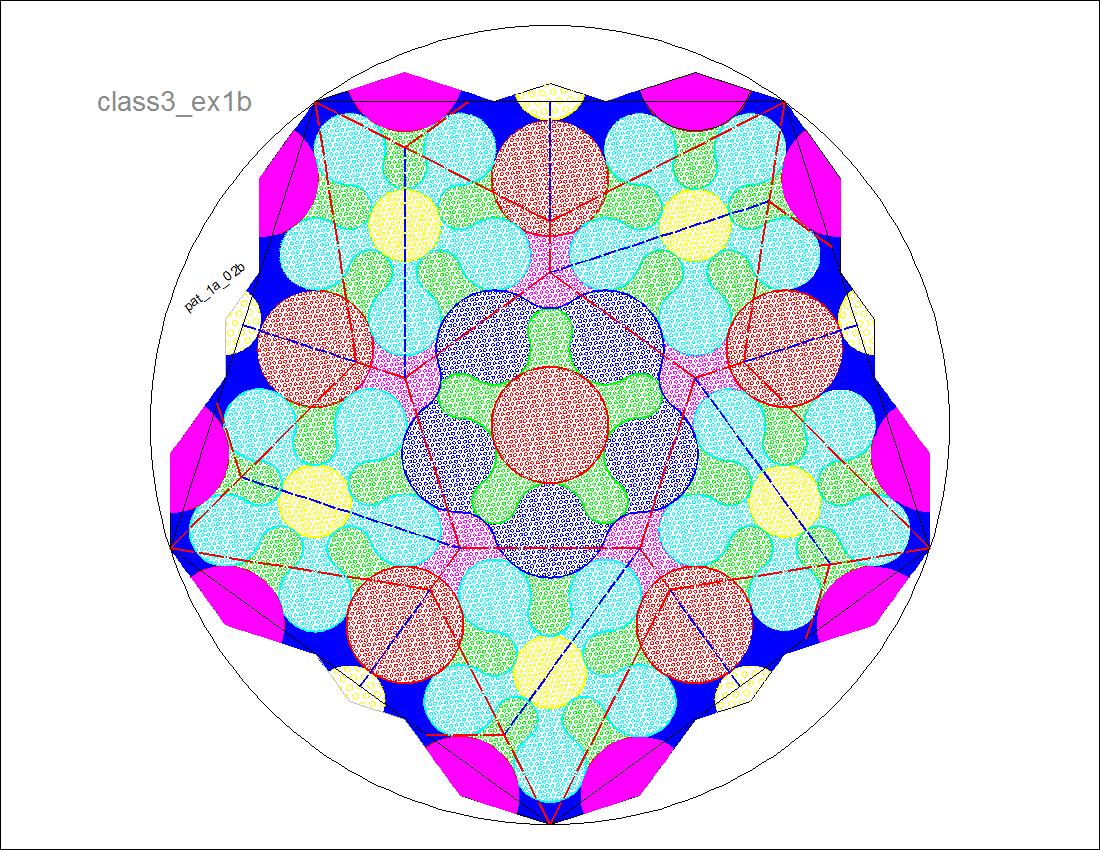
      Fig. 3-9A  Dimension for "F" & "G"
         click to enlarge & print
mod2_f+g.jpg
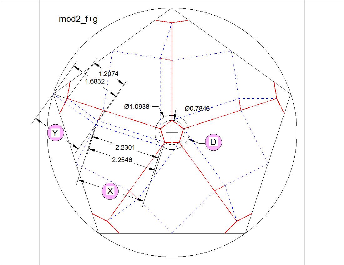
      Fig. 3-9B  Parameter Gra[h
         click to enlarge & print
mod2_param.jpg

The diagrams for case "F" and "G" are drawn on the same drawing.
In the drawing, "F" "G"
length of "X" : 2.2546 2.2301
length of "Y" : 1.6832 1.2074
diameter of the base pentagon 1.0938 0.7846
( X - D) 1.1608 1.4455
( X - D) - Y -0.5224 0.2381
This set of data are plotted in a graph , parameters shown in different colors.
Note the values of ( X - D) - Y. They are the distance of overlapping we are looking for.
The point where RED colored line intersects with ordinate value = 0 is the point
where the tip of the star touches the base pentagon.
For the actual choice of base pentagon dimension, this point is moved slightly
to the left to be safe. Its value is 0.958. The diagram using this diameter is shown below.
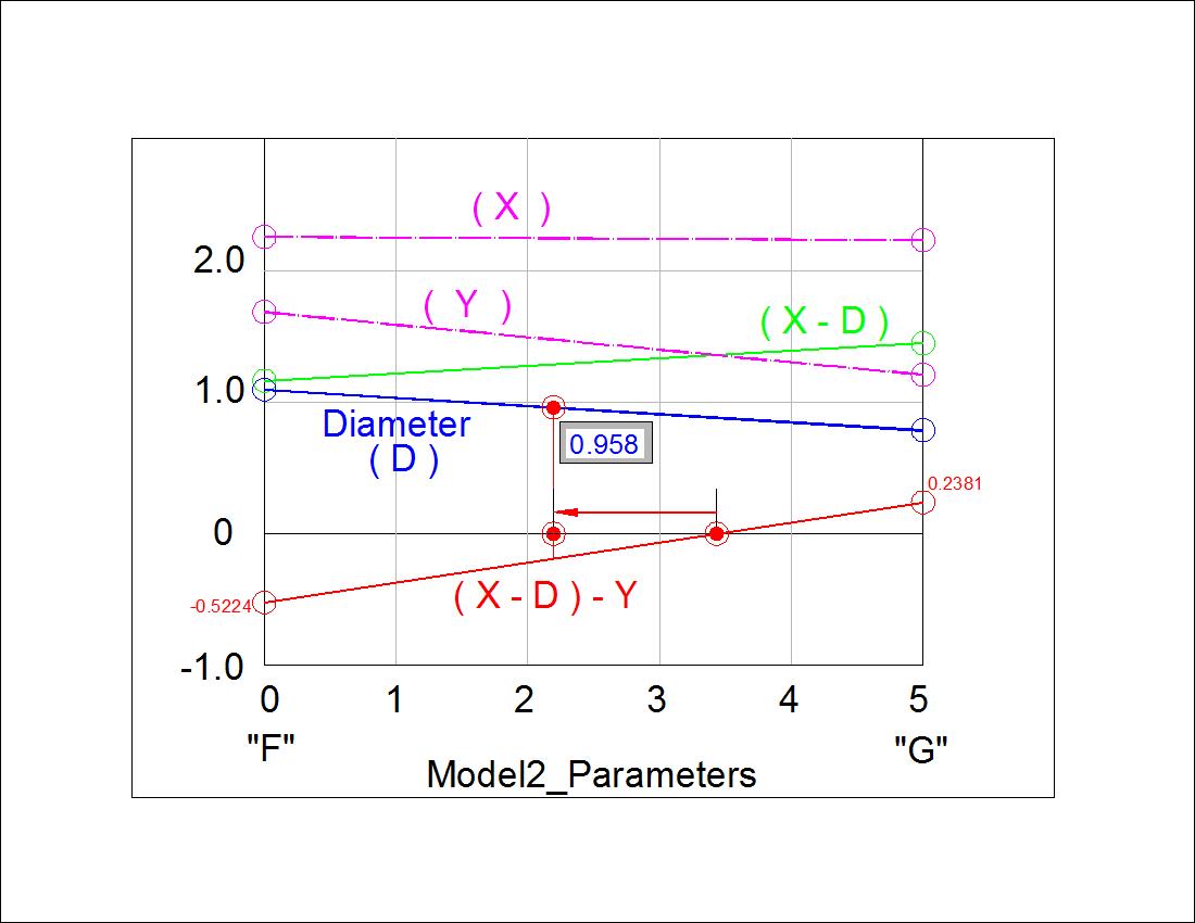
      Fig. 3-10  Model-II base
         click to enlarge & print
mod2_final.jpg

The final diagram for Model-II is created by inserting this diagram on the separately
prepared five axis symmetric image drawing.
For this exercise another pattern is printed on the back side. Notice that the pattern
on the back side is the mirror image of the same pattern with respect to the horizontal axis
through the center.
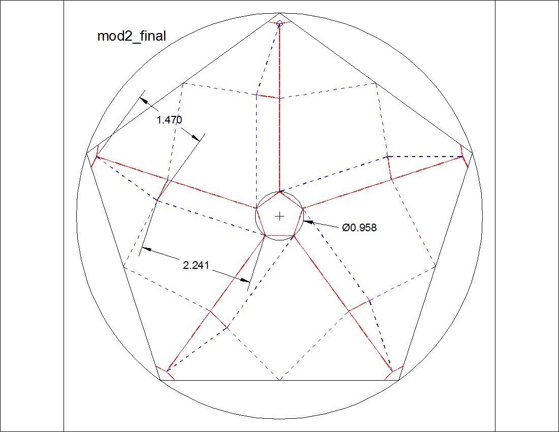
    Fig. 3-11A   Pattern Diagram - Front
         click here to enlarge
i
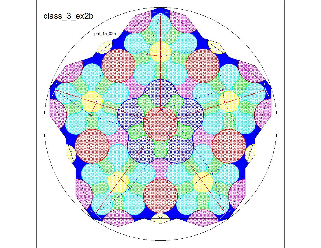
     Fig. 3-11B  Pattern Diagram - Back
         click here to enlarge
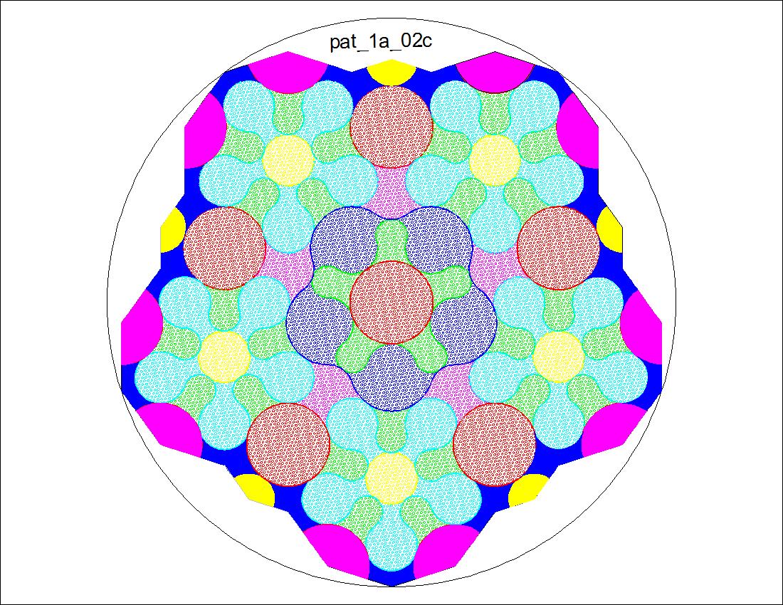
i

References

  1. Montroll, John.: Galaxy of Origami Stars,ISBN-10:1480103047,John Montroll , 2012 .
  2. Project F.: Origami - Nejiri Ori (in Japanese). Seibundo-Shinkosha,Tokyo,ISBN978-4-416-31200-1,2012 .
    Note: Project F: group of three persons-Satoko Saito, Taiko Niwa, Tomoko Fuse