click to enlarge & print
click to enlarge & print
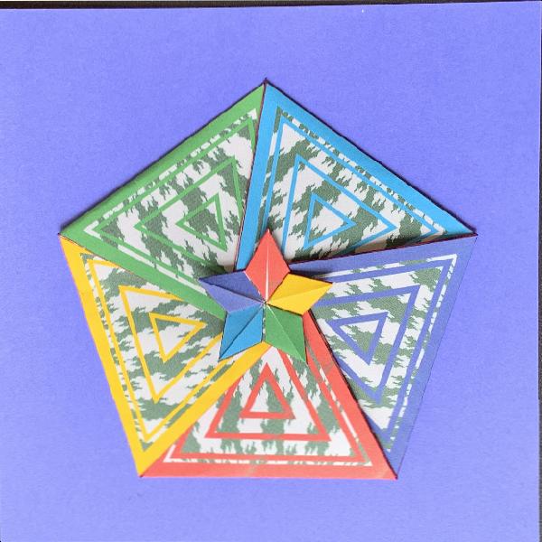
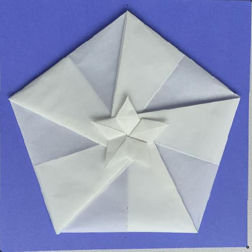
In this class we make a pentagon medal with an internal star at the center. To help the attendant to understand the folding diagram, a rectangular vellum sheet is used in a practice folding exercise. Result shown in Fig 1-1. The final target is to make a nice art piece as shown in Fig 1-2 using a paper with folding lines and five axis symmetric pattern printed. |
| Fig.1-1 Vellum Practice Fold result click to enlarge & print |
Fig.1-2 Final Fold appearance click to enlarge & print |
The first step is to cut out a pentagon from a square or rectangular paper. Here a commercially available light weight vellum paper is used. The procedure is shown in the following web site. "How to Make a Decagon" URL: http://origami.oschene.com/cp/DEcagon%20SCP.pdf by Philip Chapman-Bell . The reason I like this method is that most of the lines created in the process is used effectively when this model is folded. At the end of the original PDF file, a small drawing is added to show the discrepancy of this method against the exact pentagon geometry. |
| Fig. 1-3 Make pentagon Steps click here to enlarge 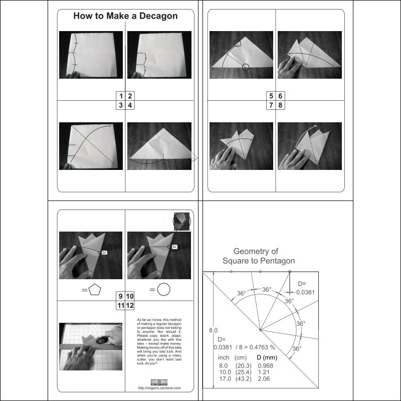 |
For clarity purposes, the front side of the paper is shown in white, and back side in black. The whole process is described in 16 steps on 2 pages as shown in Fig 1-4A & Fig 1-4B. In the drawing "red" color denotes "mountain (Yama) fold", and "blue", "valley (Tani)". |
| Fig. 1-4A Page-1 click here to see PDF 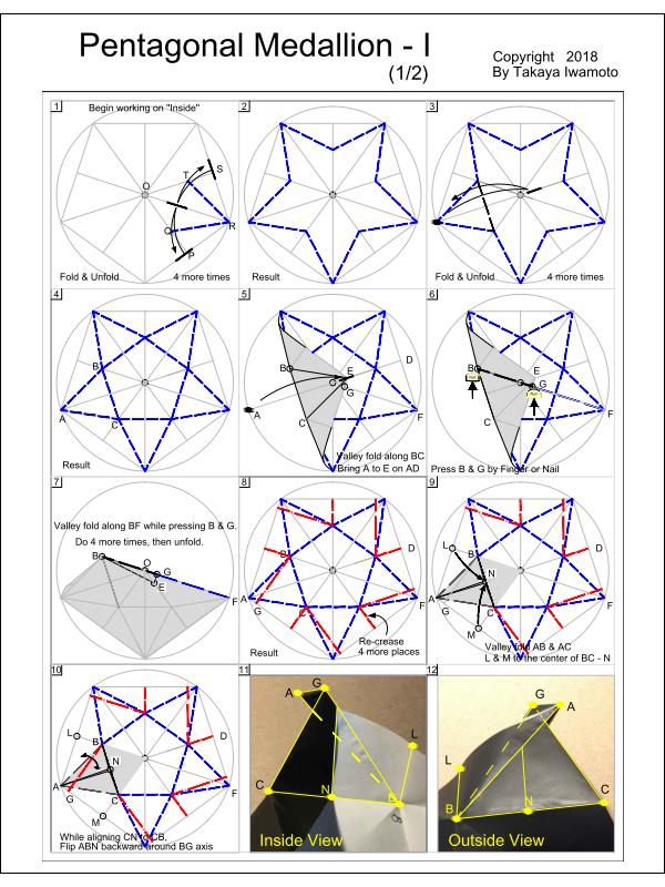 |
Fig. 1-4B Page-2 click here to see PDF 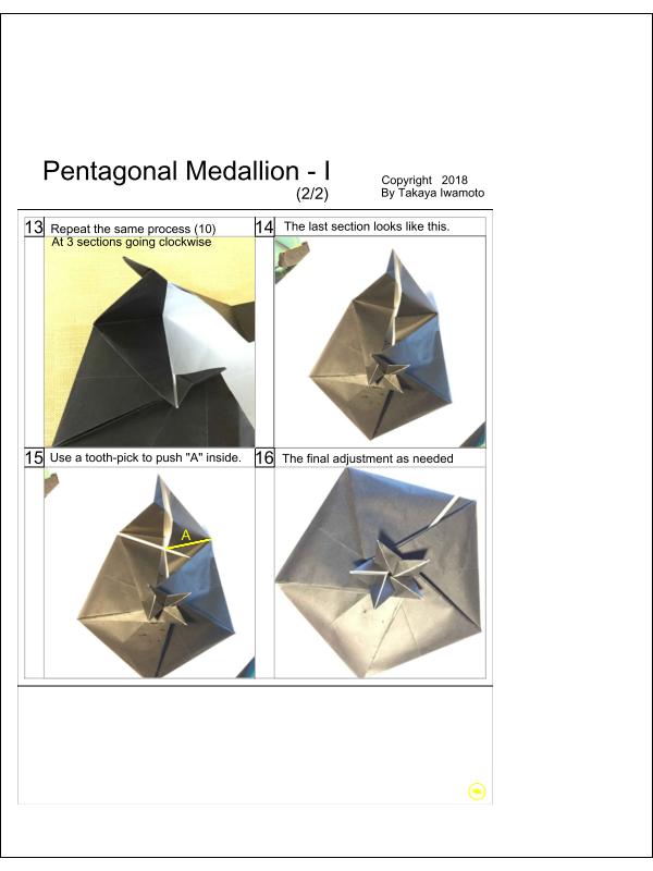 |
First fix the printed paper atop a heavy weight paper using tape. Then score all the red and blue lines using a ruler and a ball point pen. After scoring is done, peel off the scored paper. Using a scissor, cut along the outer pentagon boundary lines. Precrease mountain fold lines, then valley fold lines. Construction is similar to the process used in the vellum exercise session. |
| Fig. 1-5A Spiral click here to enlarge 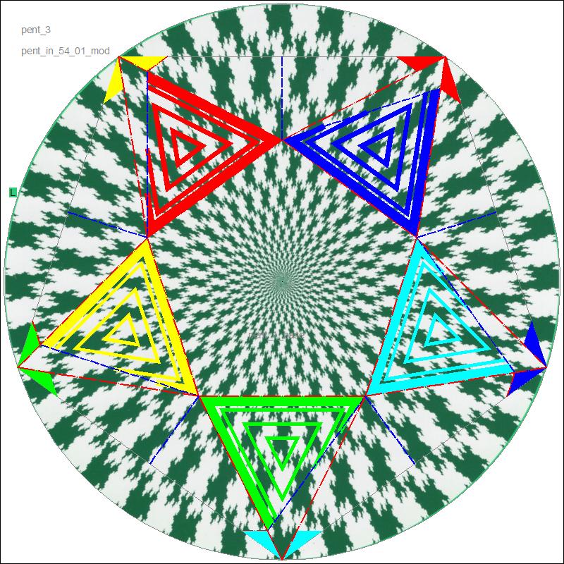 |
Fig. 1-5B Folding Diagram click here to enlarge 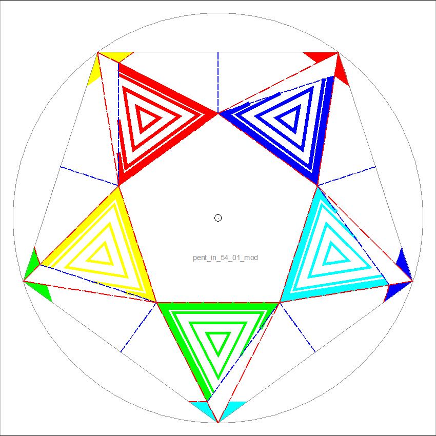 |
If you observe the two pictures above (Fig 1-5A & 5B), it is clear that Fig 1-5A is a composite of one symmetric image and Fig 1-5B. This suggests that anyone can create his own folding diagram if Fig 1-5B is printed over any image available. |
In this class we make a pentagon medal with an opening at the center. To help the attendant to understand the folding diagram, a rectangular vellum sheet is used in a practice folding exercise. Result shown in Fig 2-1. The final target is to make a nice art piece as shown in Fig 2-2 using a paper with folding lines and five axis symmetric pattern printed. |
| Fig.2-1 Vellum Practice Fold result click to enlarge & print 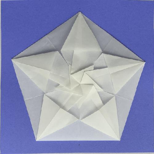 |
Fig.2-2 Final Fold appearance click to enlarge & print 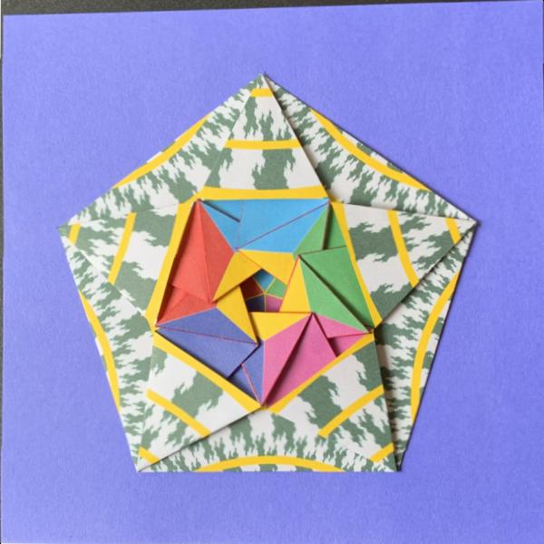 |
The first step is to cut out a pentagon from a square or rectangular paper. Here a commercially available light weight vellum paper is used. The procedure is shown in the following web site. "How to Make a Decagon" URL: http://origami.oschene.com/cp/DEcagon%20SCP.pdf by Philip Chapman-Bell . The reason I like this method is that most of the lines created in the process is used effectively when this model is folded. At the end of the original PDF file, a small drawing is added to show the discrepancy of this method against the exact pentagon geometry. |
| Fig. 2-3 Make pentagon Steps click here to enlarge |
For clarity purposes, the front side of the paper is shown in white, and back side in gray. The whole process is described in 16 steps on 2 pages as shown in Fig 2-4A & Fig 2-4B. In the drawing "red" color denotes "mountain (Yama) fold", and "blue", "valley (Tani)". |
| Fig. 2-4A Page-1 click here to see PDF 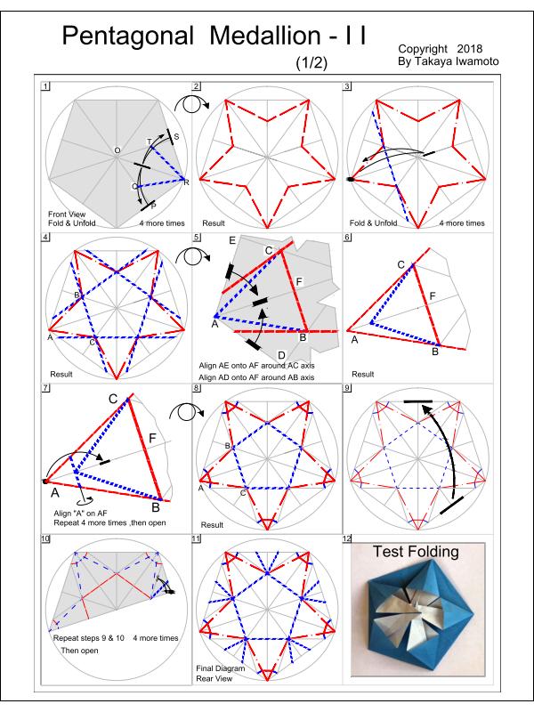 |
Fig. 2-4B Page-2 click here to see PDF 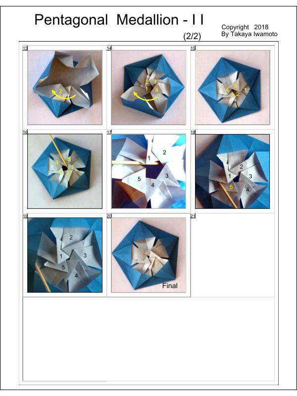 |
The paper prepared for this model has both front and back printed. The pattern on one side (Fig 2-5A) is a spiral pattern with multiple concentric circles and this is the outside pattern in the finished model. The other side (Fig 2-5B) has folding lines and the colored sections ,which is the interior pattern of the model. First fix the printed paper atop a heavy weight paper using tape. Then score all the red and blue lines using a ruler and a ball point pen. After scoring is done, peel off the scored paper. Using a scissor, cut along the outer pentagon boundary lines. Precrease mountain fold lines, then valley fold lines. Construction is similar to the process used in the vellum exercise session. |
| Fig. 2-5A Spiral Pattern click here to enlarge 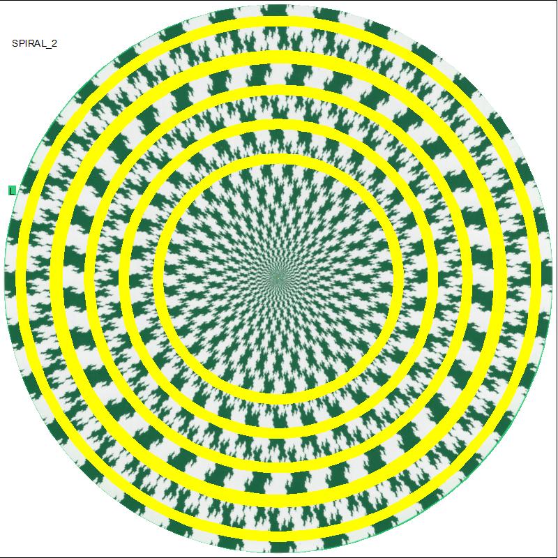 |
Fig. 2-5B Inside Pattern & Diagram click here to enlarge 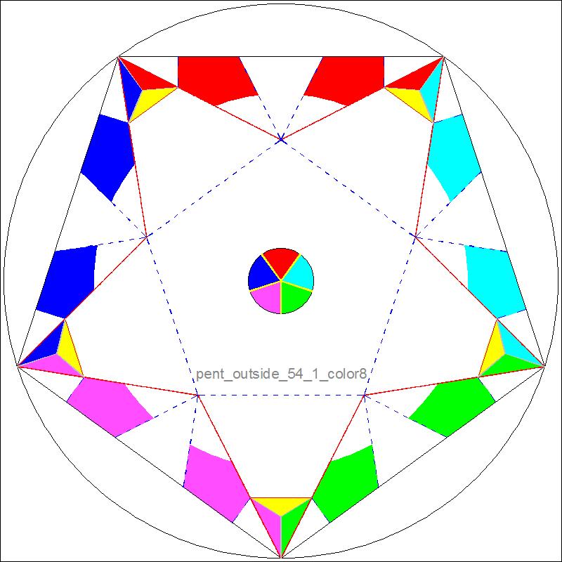 |
It is very important that the centers of the two images above must be located very close. If not, the symmetry of the folded model is lost and the overall looks is not satisfactory to the eyes. |
|
There are 2 basic ways to accomplish "Twist Fold" though there are many variations based on them. Here, as an exmple, a regular pentagon is chosen for the purpose of discussion, but the same idea can be applied to any "N"-gons. Two pentagons, outer and inner, are arranged so that the line connecting the center point and each apex of the inner pentagon passes through ,either the apex of the outer pentagon (Type-I) or the mid-point of the outer pentagon's side (Type-II). We also observe that in both cases angles are divided into 4 equal parts, at each mid-point of the side (Type-II) or at each apex (Type-I). So the each angle is Type-I 108/4 = 27 degrees Type-II 180/4 = 45 degrees Typical diagrams and their dimensions are shown in the following figures. |
| Fig. 3-1A Type -I diagram click to enlarge & print 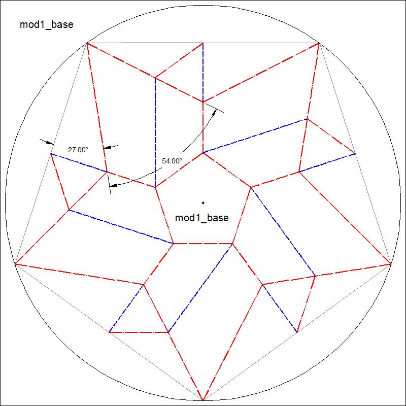 |
Fig. 3-1B Type-I appearance click to enlarge & print 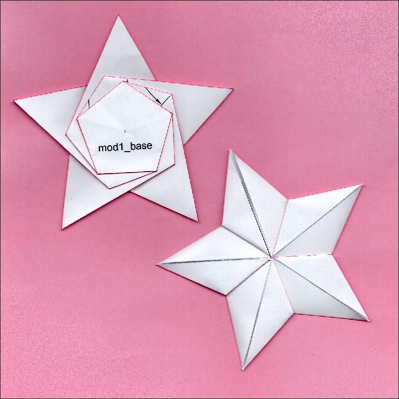 |
| Fig. 3-2A Type-II diagram click to enlarge & print  |
Fig. 3-2B Type-II appearance click to enlarge & print 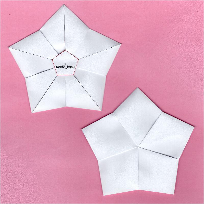 |
Here we will discuss how to apply some variations to these base model and obtain the aesthetically satisfying models . A few examples are shown in Fig 3-3A & 3B. Fig 3-3A: note that radii of the star in front and pentagon in the back are the same length. Fig 3-3B: note two overlapping pentagons at the center area. |
| Fig. 3-3A Model (I) click to enlarge & print 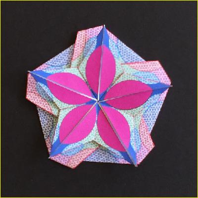 |
Fig. 3-3B Model (II) click to enlarge & print 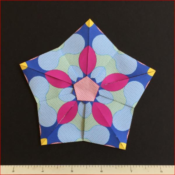 |
Here we will discuss how to apply some variations to these base model and obtain the aesthetically satisfying models . A few examples are shown in Fig 3-3A & 3B. Fig 3-3A: note that radii of the star in front and pentagon in the back are the same length. Fig 3-3B: note two overlapping pentagons at the center area. |
| Fig.3-4A Type-I Dimension click to enlarge & print 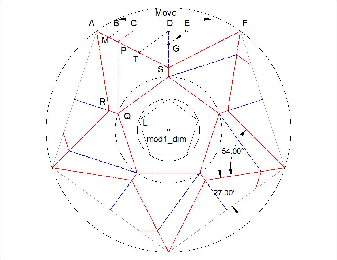 |
Fig. 3-4B Type-II Dimension click to enlarge & print 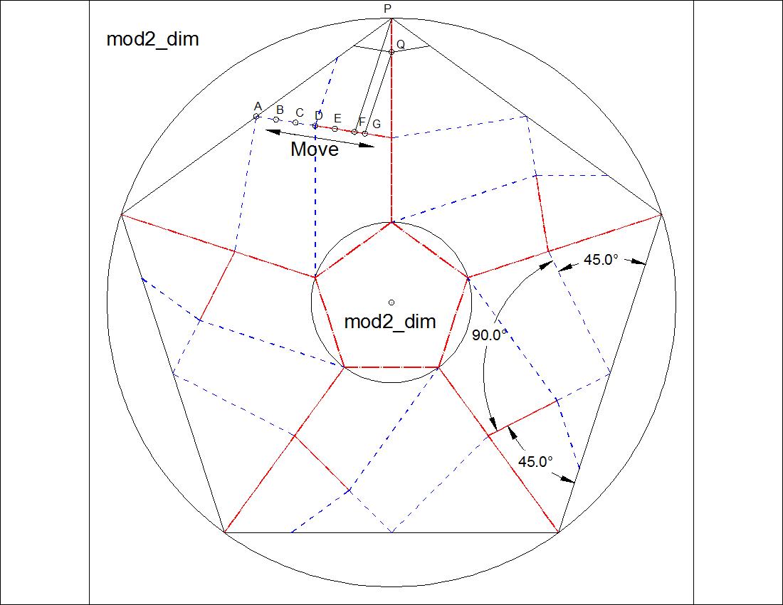 |
| Fig. 3-5A Type-I Group-Front Face click to enlarge & print 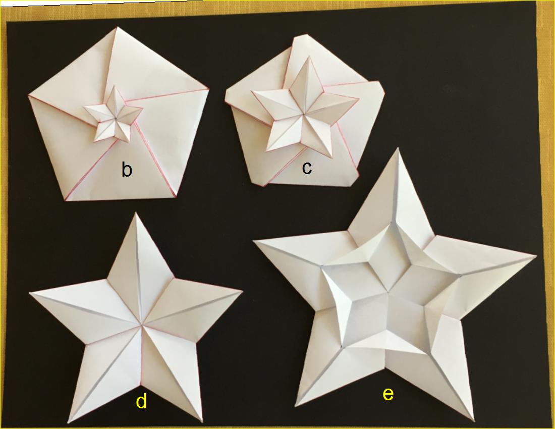 |
Fig. 3-5B Type-I Group-Back Face click to enlarge & print 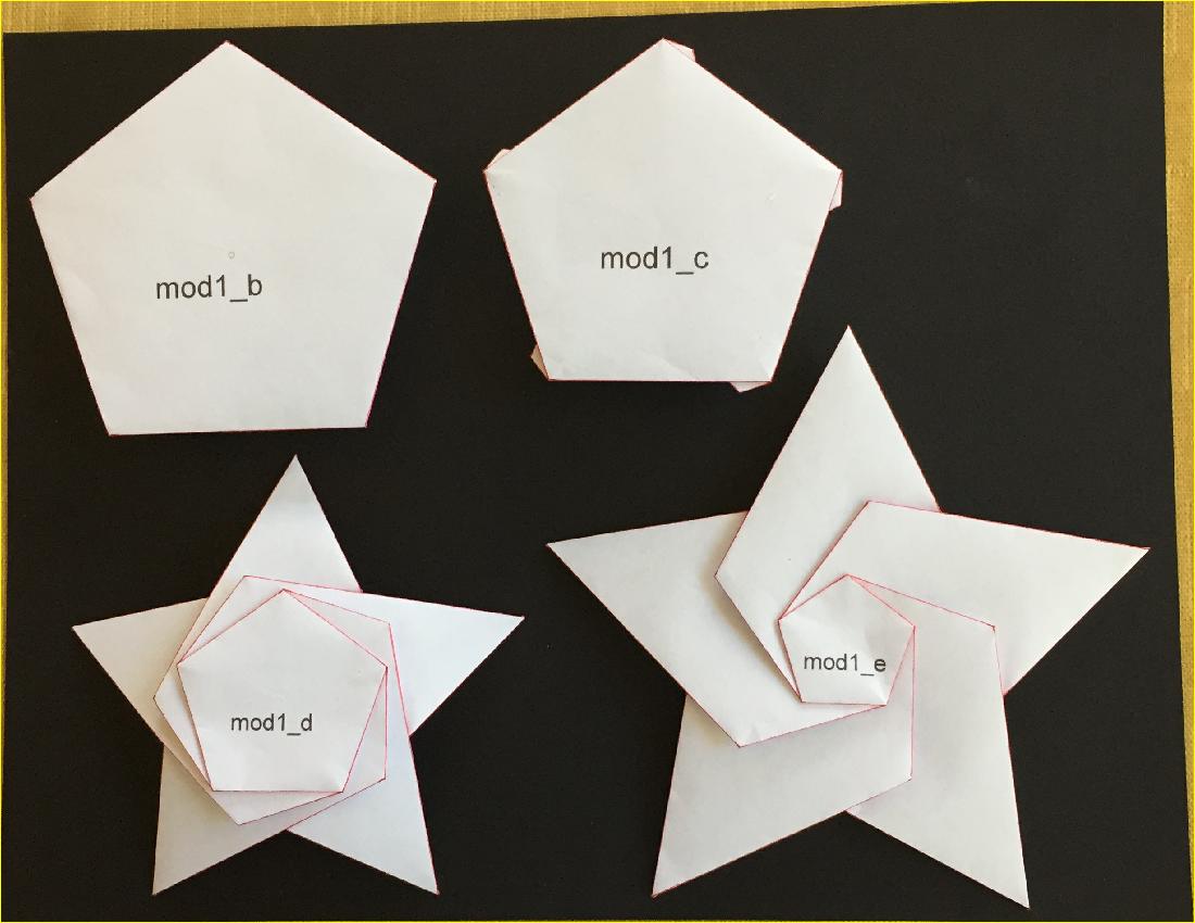 |
| Fig. 3-6A Type-I "B" diagram click to enlarge & print 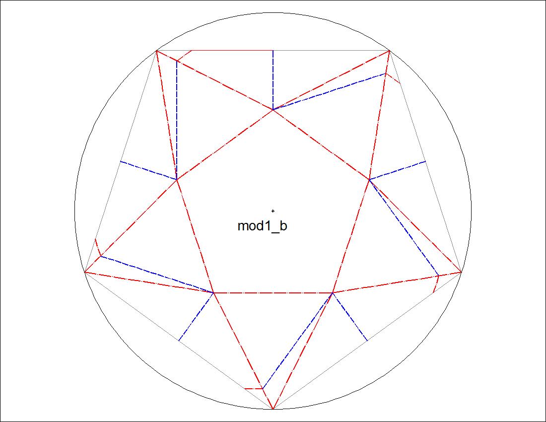 |
Fig. 3-6B Type-I "C" diagram click to enlarge & print 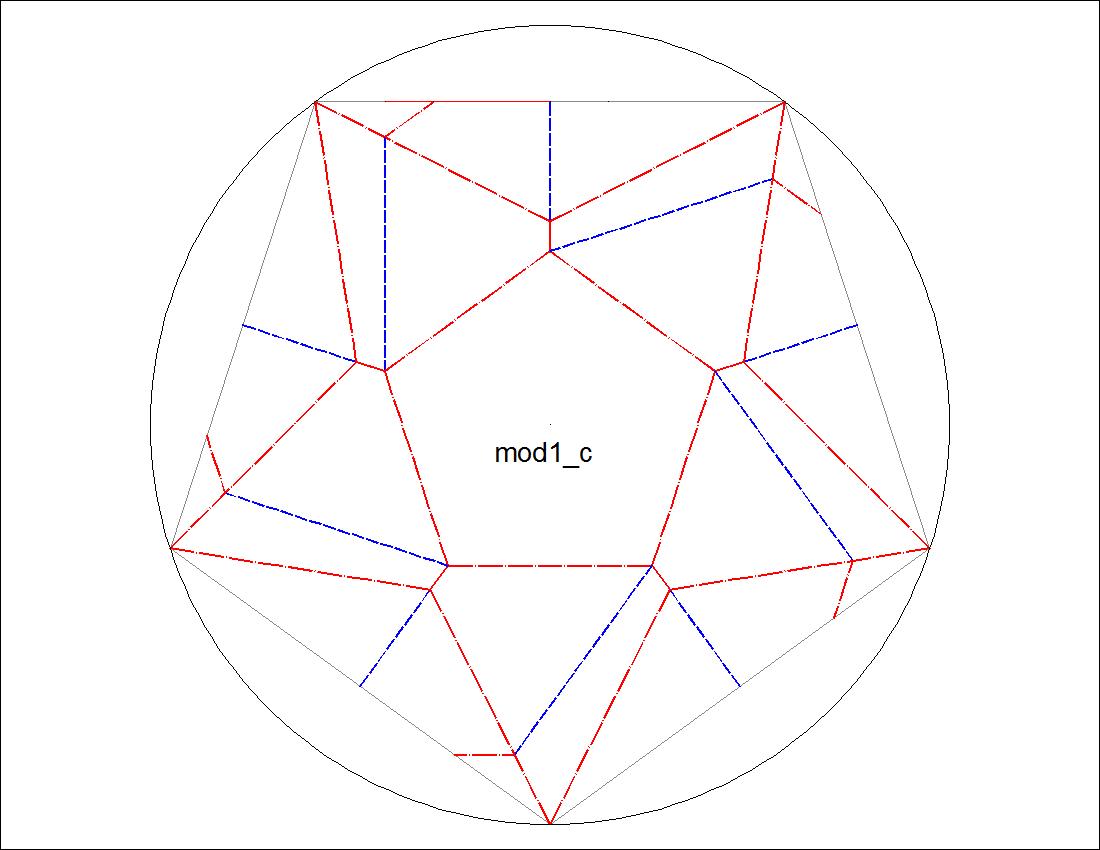 |
| Fig. 3-6C Type-I "D" diagram click to enlarge & print 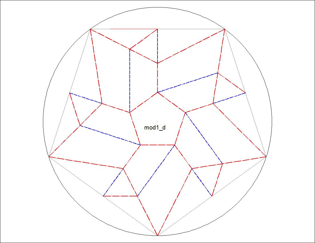 |
Fig. 3-6D Type-I "E" diagram click to enlarge & print 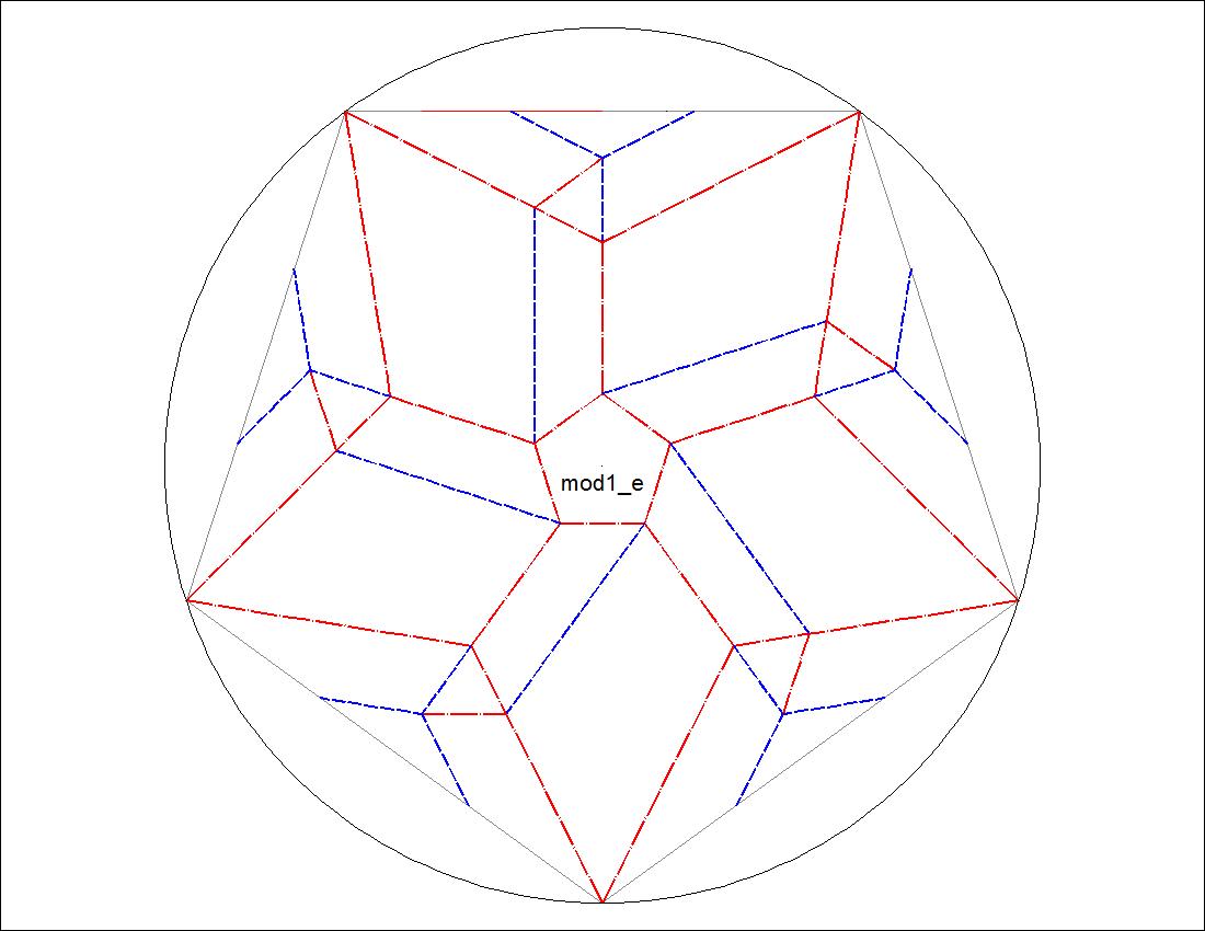 |
| Fig. 3-7A Type-II Group-Front Face click to enlarge & print 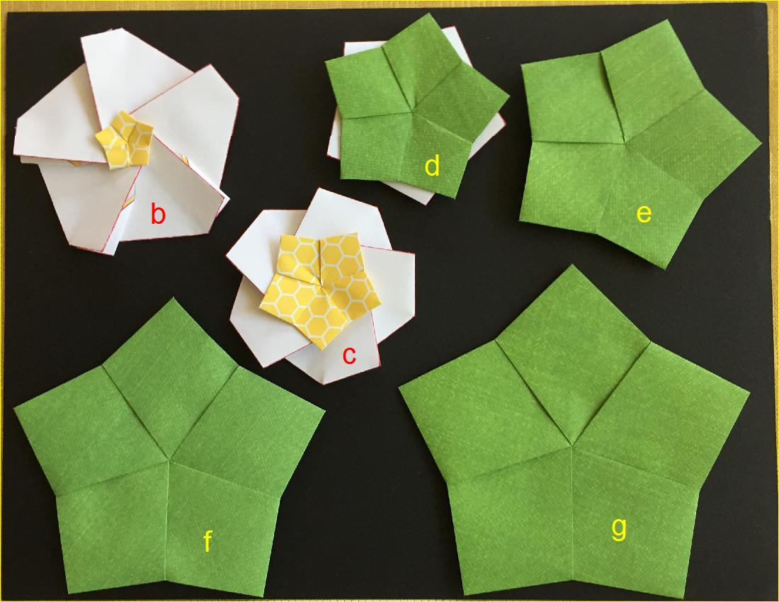 |
Fig. 3-7B Type-II Group-Back Face click to enlarge & print 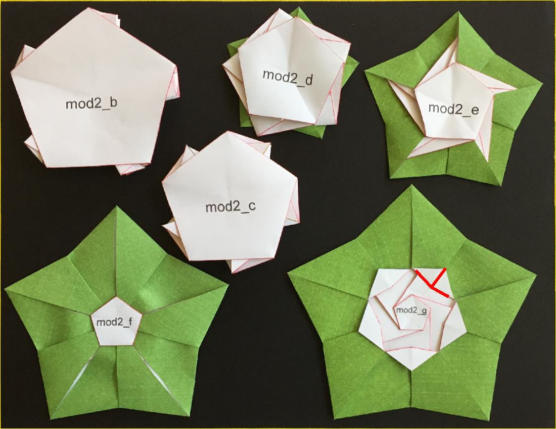 |
| Fig. 3-8A Type-II "B" diagram click to enlarge & print 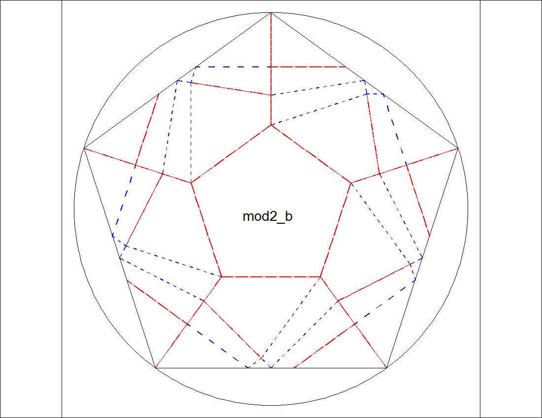 |
Fig. 3-8B Type-II "C" diagram click to enlarge & print 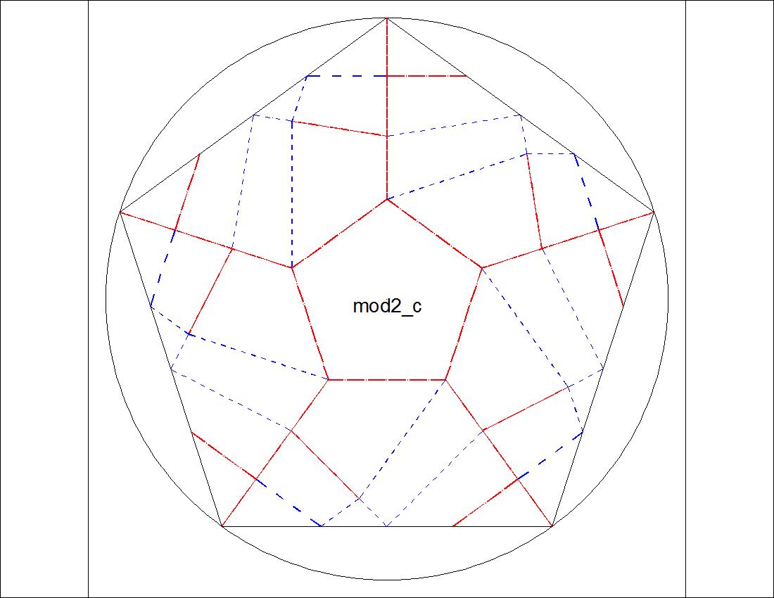 |
| Fig. 3-8C Type-II "D" diagram click to enlarge & print 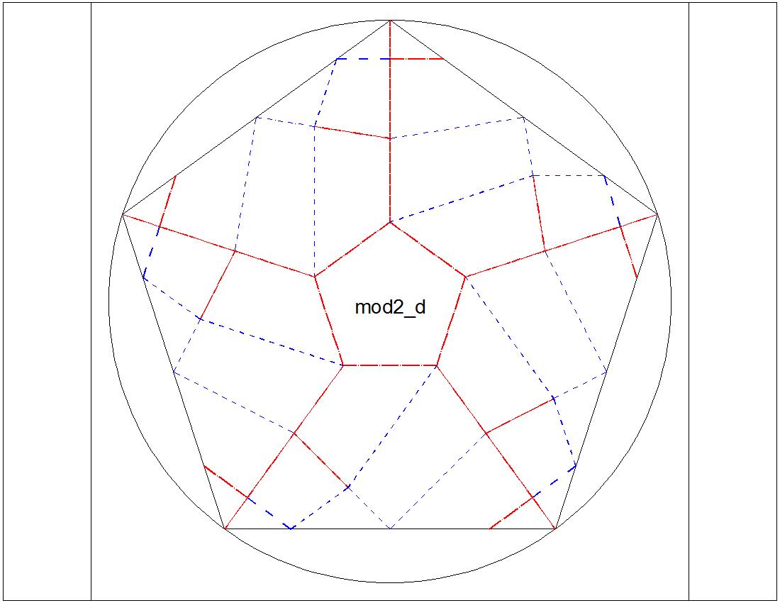 |
Fig. 3-8D Type-II "E" diagram click to enlarge & print 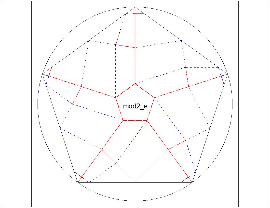 |
| Fig. 3-8E Type-II "F" diagram click to enlarge & print 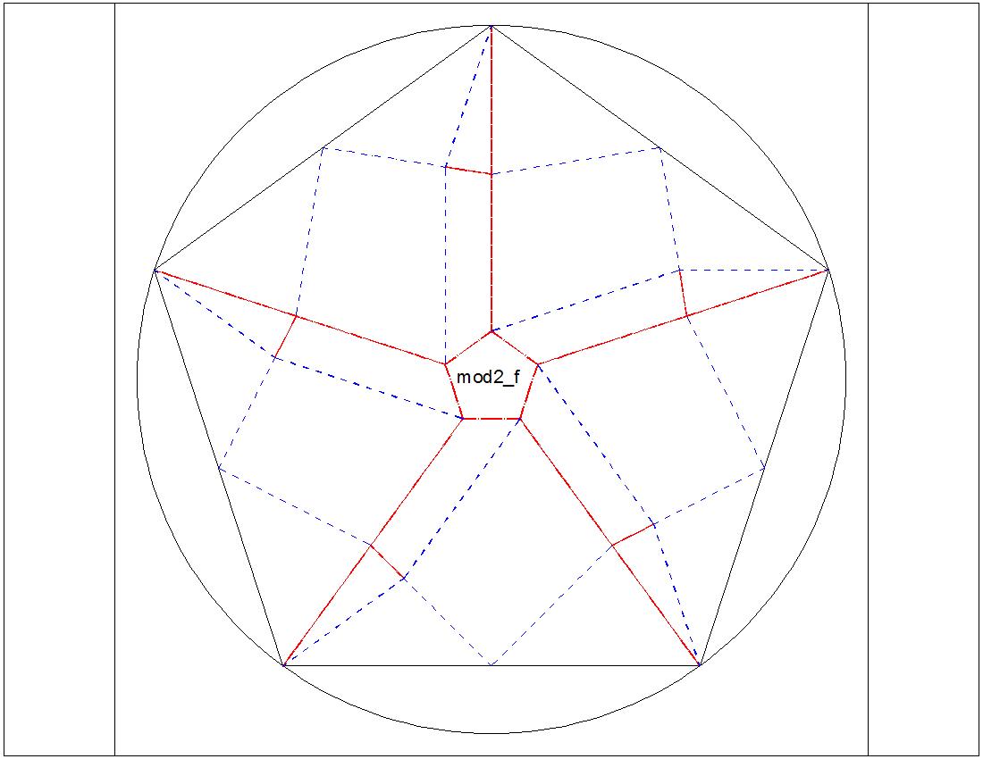 |
Fig. 3-8F Type-II "G" diagram click to enlarge & print 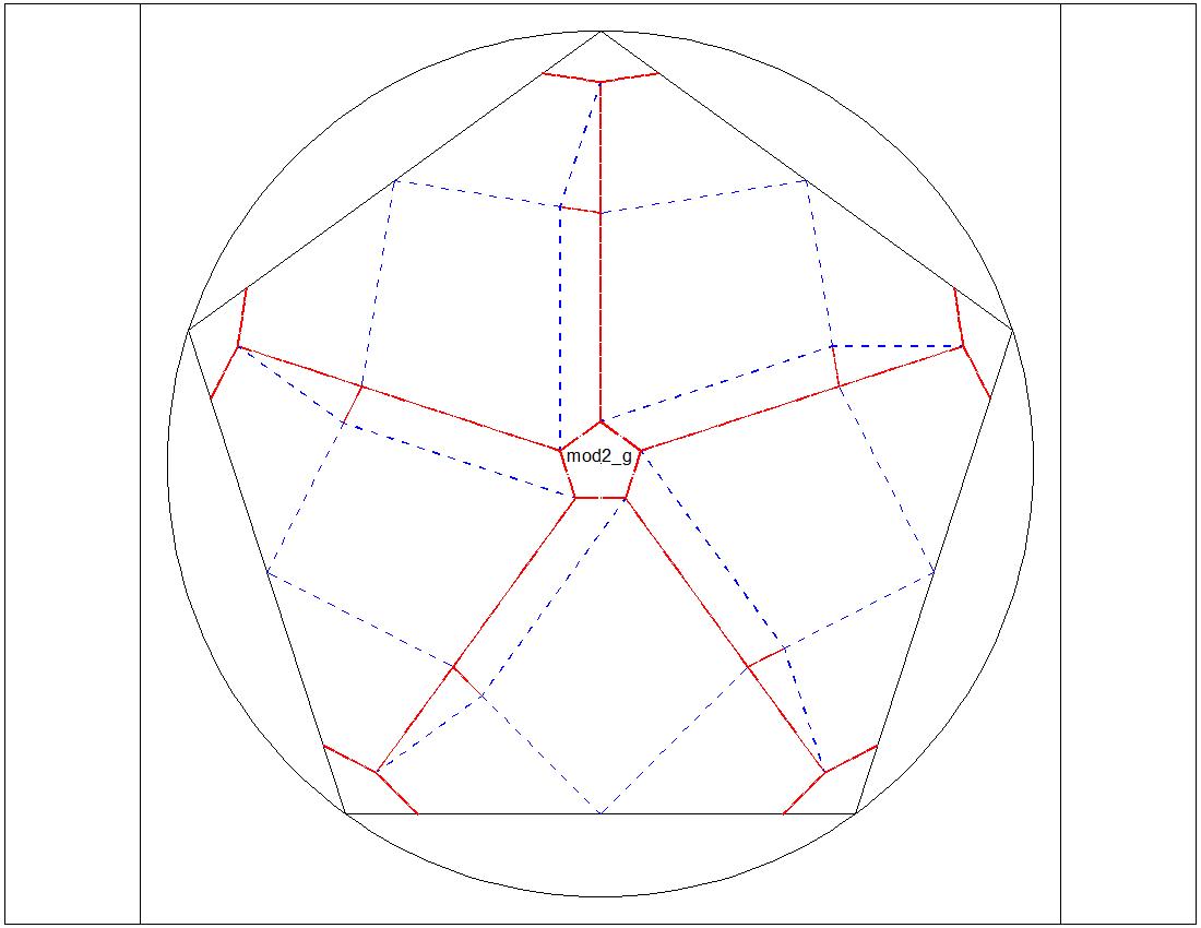 |
|
| Fig. 3-9A Dimension for "B" & "D" click to enlarge & print 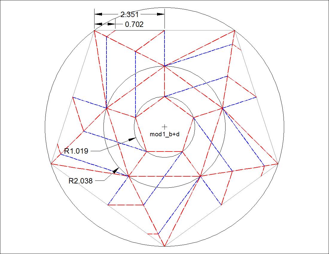 |
Fig. 3-9B Parameter Graph click to enlarge & print 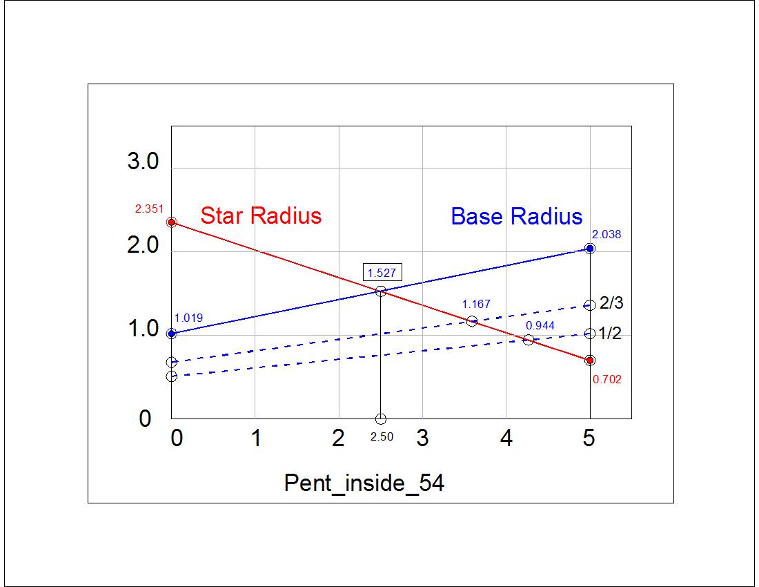 |
|
| Fig. 3-10A Model-I base diagram click to enlarge & print 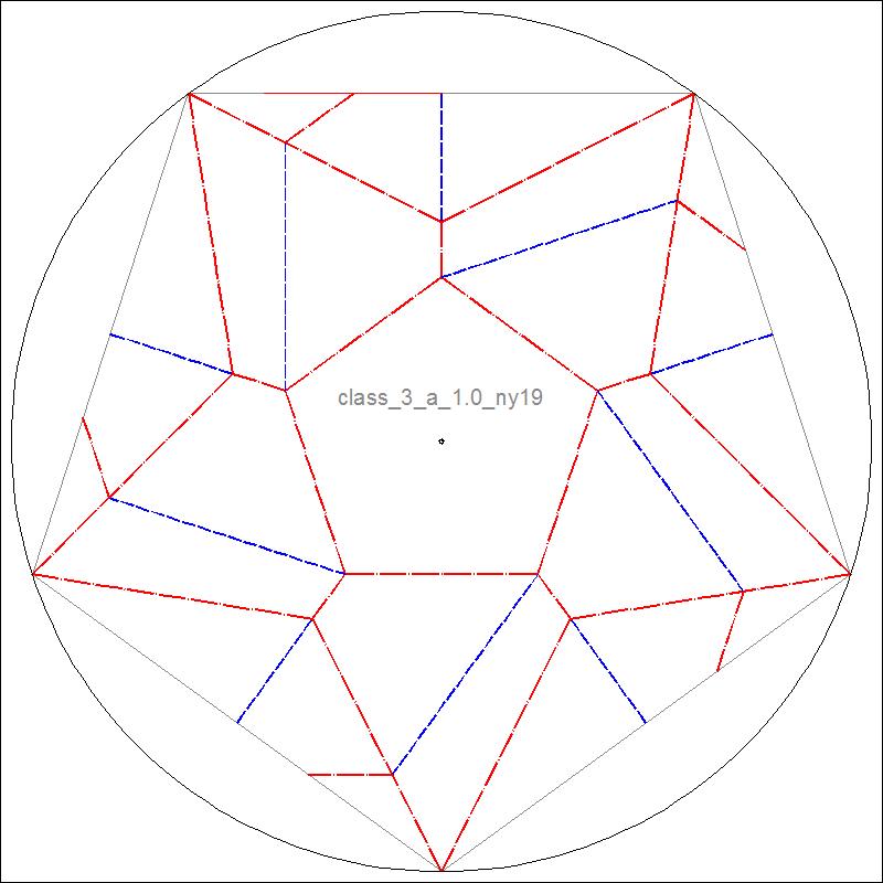 |
Fig. 3-10A Model Folded click to enlarge & print 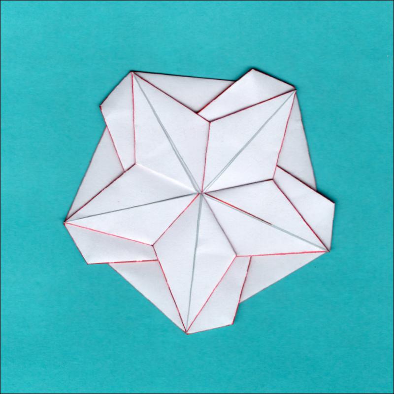 |
Fig. 3-10B Example Diagram click to enlarge & print 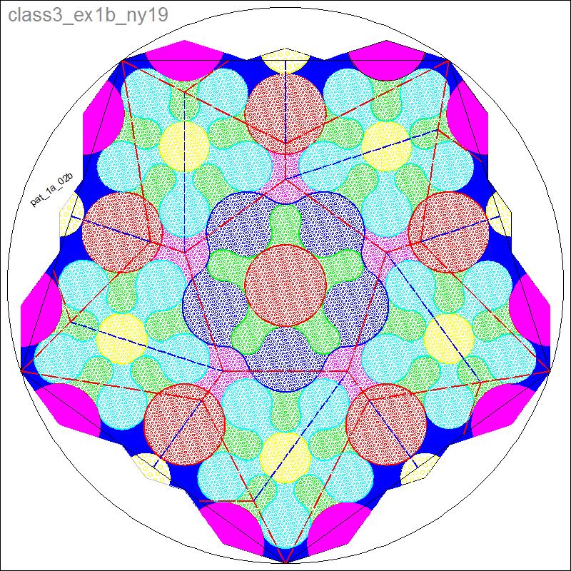 |
| Fig. 3-11A Dimension for "F" & "G" click to enlarge & print 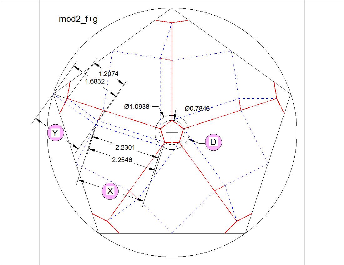 |
Fig. 3-11B Parameter Gra[h click to enlarge & print 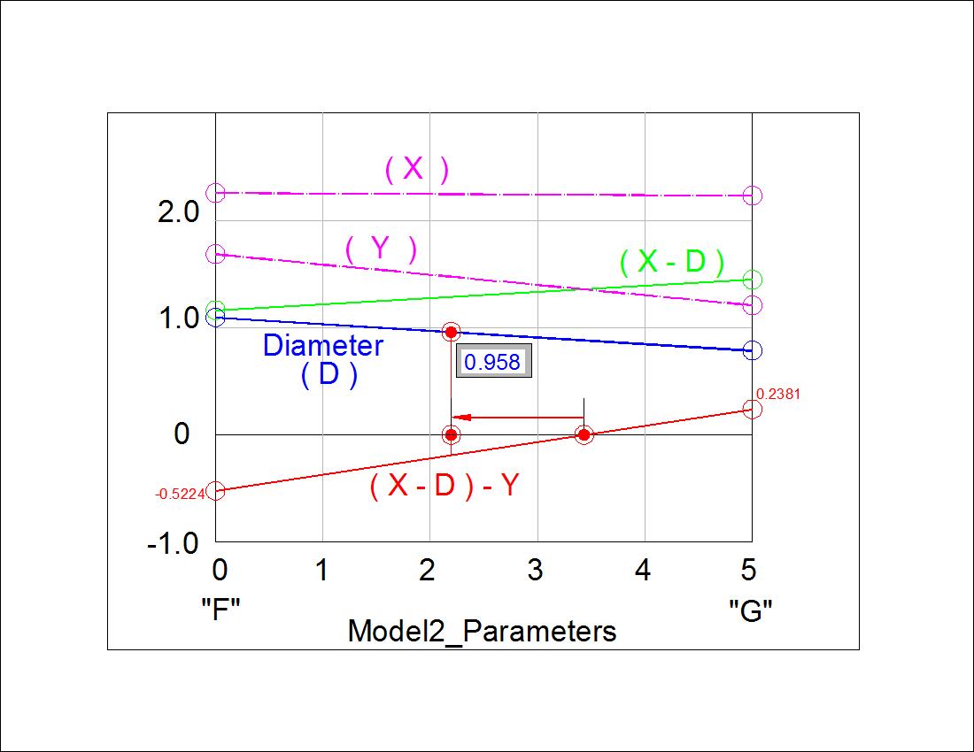 |
|
| Fig. 3-12A Model-II base click to enlarge & print 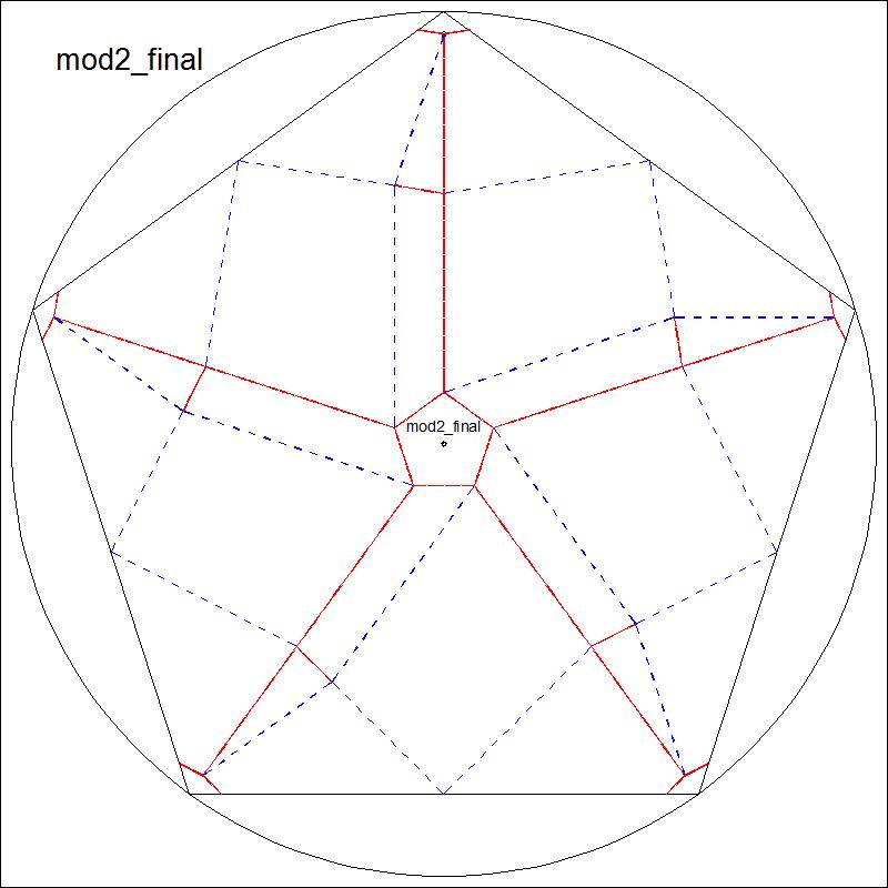 |
Fig. 3-12B Folded Model click to enlarge & print 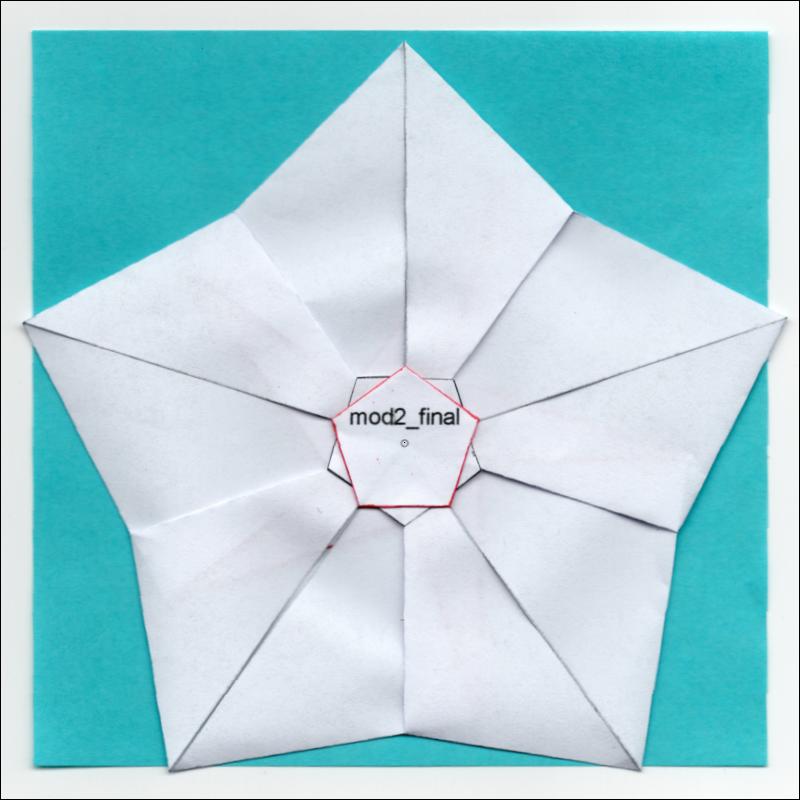 |
|
| Fig. 3-13A Pattern Diagram - Front click here to enlarge 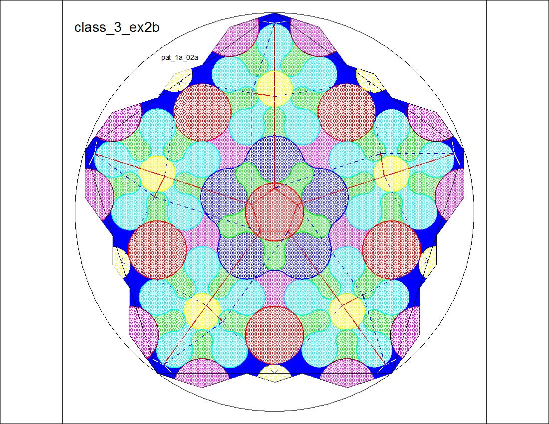 |
Fig. 3-13B Pattern Diagram - Back click here to enlarge  |