How to draw a real Chicken Egg.
In the previous topic All Curves are made up of many circles we have shown that an ellipse
can be drawn approximately by using an evolute made up of 5 points.
The smart readers must have by now noticed the similarity between the shapes of a chicken egg
and an ellipse. In this section, we will discuss how a real chicken egg shape can be handled
in a very similar fashion.
Now for our argument sake, let us place the flatter side of a chicken egg at the bottom
and the protruded side at the top. After all that is how Christopher Columbus let the famous
"Columbus' Egg" stand upright on the flat table. It is interesting to note that most of the pictures
in books on Bird's egg shape use just the opposite convention.
Then the noticeable difference of shape between a chicken egg and ellipse is that the radius of
evolute on the top does not exceeds that of the bottom.
But before getting into how to handle "a real chicken shape", let us become more familiar with
a family of much simpler egg-like shape , which can be handled relatively easily by simple
"compass and ruler" operation.
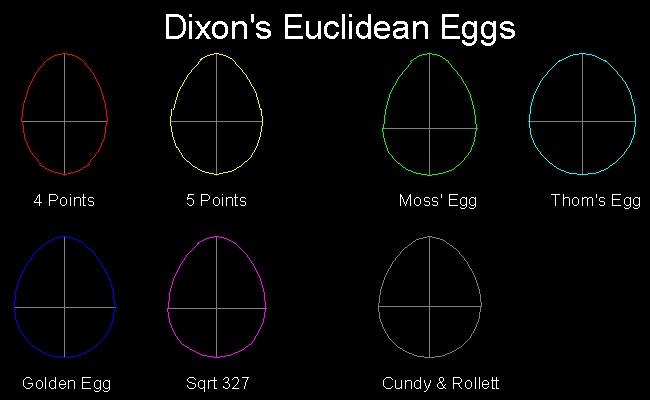
Robert Dixon (Ref. 1) shows several kinds of egg-shape, which he called "Euclidean Egg"
because all of them can be drawn by compasses and ruler.
All 7 shapes are shown in the drawing below. Naming convention follows Ref.1.
Out of 7 shape types, 5 types use only 3 circles, and the rest, 4 and 5 circles, each.
Seven Euclidean eggs
************************ Download this image(jpg file format) ********************** ************************ Download this drawing(DWG format) **********************
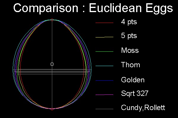
In order to see the difference of shapes among all these curves, it is necessary to "normalize"
(i.e. make them equally scaled) the drawing.
The height of each egg is set to the same value, and the bottom point of each egg is placed on
the horizontal level for comparison.
The vertical line is what is called "center line of revolution" in 3 dimentional space, and it is
a mirror symmetry line in two dimensional picture.
The horizontal line shows where the bulging of each egg is the maximum.
They will be used later to see how the shapes of actual chicken eggs look like.
When all of the "Euclidean egg" are placed at the same base point, it is easy to see the difference
of their shapes. This operation is made possible because they are all normalized. Height of the egg is
set to a unit value(1.0), and the middle point (0.5) is shown in the picture. We can see that the point
of the widest bulge is below this middle point. This is another important characteristic of egg's shape.
****************** compare_Euclidean_eggs.dwg **********************
Reference drawing:
Dixon's_Euclidean_eggs.dwg ----------------showing 7 Euclidean Eggs.
compare_Euclidean_eggs.dwg---------------Overwriting all Eggs at one location for comparison.
Executables for creating these drawings:
Load egg_shape.lsp ---> (load "egg_shape")
To execute: from command line: Show_Euclidean_Egg , Compare_Euclidean_Egg
How to draw Euclidean Eggs
*** 4 Points Egg ***
The naming comes from using 4 circles in its construction.
See 4 Points Egg shape drawing in animation.
Use browser's "Back" button to come back to this page.
************************ Download this drawing(DWG format) **********************
(1) Draw an upper semi_circle with unit radius centered at (0 0).
Points 3, 3' & 4 are created.
(2) Draw an arc 42 with its center at 3', radius = 3'4 = S2. The arc starts at 4 and ends at 2 on x-axis .
Do the same for 3 on left hand side. Points 2 , 2' & 6 are created.
(3) Draw a circle with its center at (0 0) and diameter 2-2' = 2S2 - 2. It intersects Y-axis at point 1.
(4) Draw the "red" arc with its center at 1, radius = 2S2 - 2.
(5) Draw the "yellow" arc with its center at 2, radius = 3/S2 - 1
(6) Draw the "green" arc with its center at 3, radius = 2
(7) Draw the "cyan" arc with its center at 4 ,radius = 2 - S2
*Note: In drawing circle in step 7, the line length 4-6 is used as radius.
Reference drawing:
egg_Euclidean_4pt.dwg ----------------Drawing file created according to the steps above.
egg_Euclidean_4pt_normalized.dwg------Height is normalized to a unit value.
egg_Euclidean_4pt_normalized_1.dwg----Erased texts & construction lines
Executables for creating this drawing:
Load egg_draw.lsp ---> (load "egg_draw")
To execute: from command line: Draw_4pt
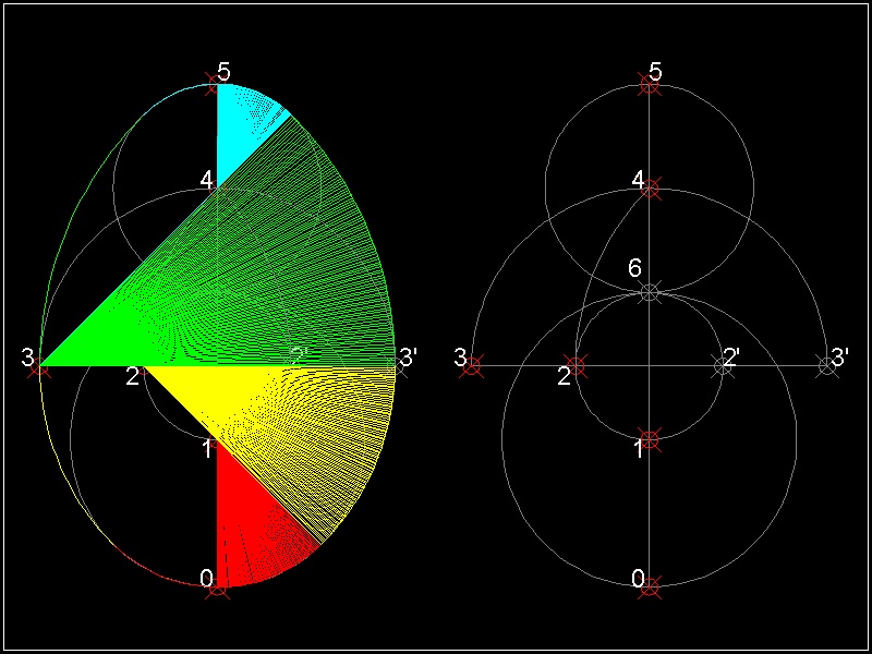
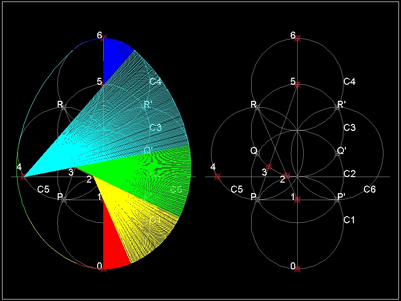
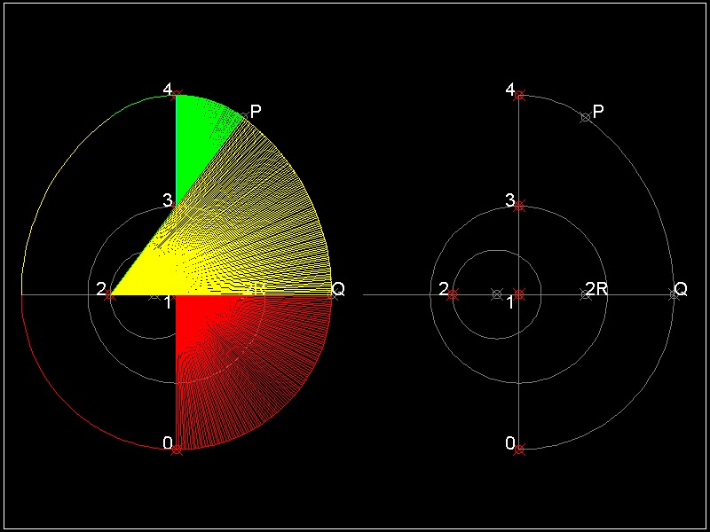
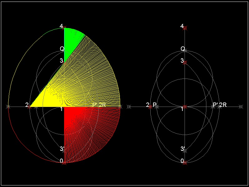
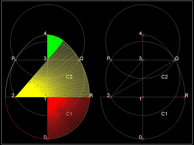
*** 5 Points Egg ***
The naming comes from using 5 circles in its construction.
See 5 Points Egg shape drawing in animation.
Use browser's "Back" button to come back to this page.
************************ Download this drawing(DWG format) **********************
(1) Draw 4 unit circles with unit distance apart and call them C1, C2 ,C3 & C4
These circles intersect at 6 points :P,Q,R & P',Q',R'. Line PP' cuts Y-axis at point 1.
Circles C1 ,C3 & C4 cuts Y-axis at point 0 ,5 & 6,respectively.
(2) Draw lines P5 and R1.
Intersection with C3 is point 3 & 2 , respectivley.
(3) Draw a unit circle at Q and Q', and call them C5 & C6.
Intersection of C5 and Q'3 is point 4.
Five points, 1 through 5, are the center of the evolute circles.
Reference drawing:
egg_Euclidean_5pt.dwg --Drawing file created according to the steps above.
egg_Euclidean_5pt_normalized.dwg----Height is normalized to a unit value.
egg_Euclidean_5pt_normalized_1.dwg----Erased texts & construction lines
Executables for creating this drawing:
Load egg_draw.lsp ---> (load "egg_draw")
To execute: from command line: Draw_5pt_Egg
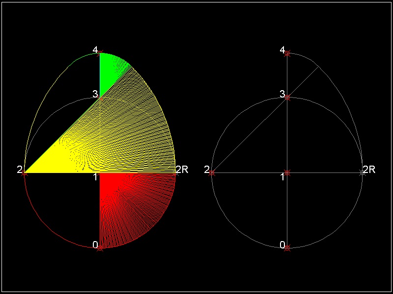
*** Moss' Egg (3 points) ***
The author does not know where this name came from.
See Moss' Egg shape drawing in animation.
Use browser's "Back" button to come back to this page.
************************ Download this drawing(DWG format) **********************
(1) Draw a unit circle with its center at ( 0 0 )
(2) Draw an arc starting from point 2R,then ends at line 23.
(3) Draw an arc on the top.
Reference drawing:
egg_Euclidean_Moss.dwg ----Drawing file created according to the steps above.
egg_Euclidean_Moss_normalized.dwg------Height is normalized to a unit value.
egg_Euclidean_Moss_normalized_1.dwg----Erased texts & construction lines
Executables for creating this drawing:
Load egg_draw.lsp ---> (load "egg_draw")
To execute: from command line: Draw_Moss_Egg
*** Thom's Egg (3 points) ***
The naming comes from "Megalithic Sites in Britain" by A.Thom (Ref.3). He wrote thatthere are 10 megalithic sites in Britain which are egg-like shaped
,and use 3-4-5 Pythagorean number as centers of the sites. It proves that 1000 years
before the earliest mathematicians of classical Greece, the people of megalithic civilization had
a practical knowledge of Geometry, and used it in their astronomical observation.
In the drawing below, triangle 1-2-3 forms 3-4-5 Pythagorean number.
See Thom's Egg shape drawing in animation.
Use browser's "Back" button to come back to this page.
************************ Download this drawing(DWG format) **********************
(1) Draw a unit circle with its center at point 1 (0 0).It cuts Y-axis at point 3
(2) Draw a circle at (-0.25 0) , radius = 0.5 . It cuts X-axis at point 2
(3) Draw a line 23. extend it to P such that 2P is twice the line length 23 .
(4) Draw an arc from P to 4,its radius = 3P
(5) Mark a point Q on X-axis such that 2P = 2Q
(6) Mark point 0 such that 10 = 1Q.
(7) Draw an arc from O to Q.
Reference drawing:
egg_Euclidean_Thom.dwg -----------Drawing file created according to the steps above.
egg_Euclidean_Thom_normalized.dwg------Height is normalized to a unit value.
egg_Euclidean_Thom_normalized_1.dwg----Erased texts & construction lines
Executables for creating this drawing: Draw_Thom
Load egg_draw.lsp ---> (load "egg_draw")
From command line: Draw_Thom
*** Golden Egg (3 points) ***
The naming comes from using golden ratio in its construction.
See Golden Ratio Egg shape drawing in animation.
Use browser's "Back" button to come back to this page.
************************ Download this drawing(DWG format) **********************
(1) Draw 3 unit circle with its center at (0 -1) ,(0 0) & (0 1) .
They cut X & Y-axis at points 0,Q,P & P'.
Point (0 0) is point 1.
(2) Draw an arc centered at P ,starting from point 0,then ends at Q.
Do the same for point P' .
This will create points 2 & 2R.
(3) Draw an arc with its center at 2,its radius = 2.0 from 3' to 3.
(4) Distance between 3 and 4 is the same as length 21 = (S5 -1)
The reason this egg is named "Golden" is that ratio of length 21 to 23 is (S5 -1)/2 ,
which is a reciprocal of well known golden ratio (S5 + 1)/2 = 1.61803.....
Reference drawing:
egg_Euclidean_golden.dwg ----------------Drawing file created according to the steps above.
egg_Euclidean_golden_normalized.dwg------Height is normalized to a unit value.
egg_Euclidean_golden_normalized_1.dwg----Erased texts & construction lines
Executables for creating this drawing:
Load egg_draw.lsp ---> (load "egg_draw")
To execute: from command line: Draw_Golden
*** Sqrt327 Egg (3 points) ***
The naming comes from the ratio of length of 3 sides of triangle used in the construction.It is S3 : 2 :S7. So the author called this egg shape sqrt 327.
See sqrt327 Egg shape drawing in animation.
Use browser's "Back" button to come back to this page.
************************ Download this drawing(DWG format) **********************
(1) Draw 2 unit circles C1 & C2 with its center at (0 0.5) and (0 1.5).
Connect intersecting points P Q. Line PQ cuts Y-axis at point 3.
C1 cuts X-axis at point 2. point (0 0) is point 1.
(2) Draw lines 23 and Q2. Locate point R on X-axis such that 2Q = 2R
(3) Draw an arc starting from point R,then ends at line 23.
(4) Draw an arc circle on the top.
(5) Draw a circle on the bottom. length 1R = length 10
The ratio of length of 3 sides of triangle 123 is S3 : 2 :S7.
Dixon named this circle S3 : 2 :S7 .
Reference drawing:
egg_Euclidean_sqrt327.dwg ----------------Drawing file created according to the steps above.
egg_Euclidean_sqrt327_normalized.dwg------Height is normalized to a unit value.
egg_Euclidean_sqrt327_normalized_1.dwg----Erased texts & construction lines
Executables for creating this drawing:
Load egg_draw.lsp ---> (load "egg_draw")
To execute: from command line: Draw_Sqrt327
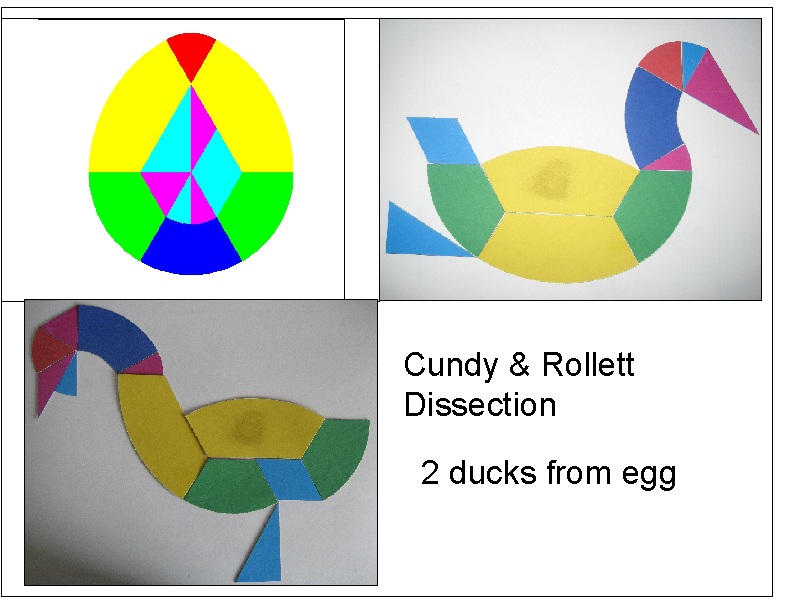
*** Cundy_Rollett Egg (3 points) ***
The naming comes from the egg shape based dissection referred in Cundy & Rollett book withthe title "Mathematical Models"(Ref 2).
This idea is shown as a varitation of a famous Chinese traditional pastime known as "tangram".
An egg is dissected into 12 pieces, and these pieces are rearranged to form the outline of birds,
ship, animals,etc. Here the author tried 2 cases of ducks.
See Cundy & Rollett Egg shape drawing in animation.
Use browser's "Back" button to come back to this page.
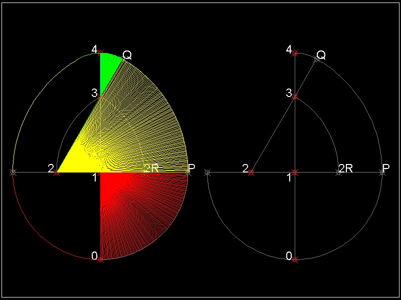
************************ Download this drawing(DWG format) **********************
(1) Draw a semi_circle with its center at point 1 (0 0) and radius = 2.0
(2) Define points 2 & 2R at unit distance from point 1.
Draw an arc with its center at 2 ,starting at 2R, ending at point 3 on Y-axis
(3) Draw a line 23. extend it to P such that 2P is 1.5 times 23 length.
(4) Draw an arc PQ with its center at 2
(5) Draw an arc from Q to 4
(6) length 10 = 1P
Reference drawing:
egg_Euclidean_Cundy_Rollett.dwg ----------------Drawing file created according to the steps above.
egg_Euclidean_Cundy_Rollett_normalized.dwg------Height is normalized to a unit value.
egg_Euclidean_Cundy_Rollett_normalized_1.dwg----Erased texts & construction lines
Executables for creating this drawing:
Load egg_draw.lsp ---> (load "egg_draw")
To execute: from command line: Draw_Cundy_Rollett_Egg
How the real chicken egg look like
*** Real Chicken Egg ***
Now let us draw the actual chicken egg shape using evolute.The steps to define evolute curve for the actual egg goes like this:
(1) Take a digital photo of a sample egg, and import to CAD.
(2) Digitize the image on CAD software.(Define the egg's shape by defining points along the
egg's curve.)
(3) connect these points and create one spline or polyline entity.
(4) Divide this spline into equal spacings (48 , for example)
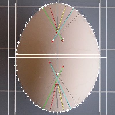
(5) At both ends draw circles passing three consecutive points,and draw lines between the
circle's center and the middle point of the 3 points' circle.
(6) Observation of the results lead to the end arc radii and Y-axis.
Evolute points #1 & #5 are defined.
(7) Divide the right half of polyline into 12 equal length . Use these points to define evolute points.
This process define evolute point #3.
(8) find evolute point #2 & #4 using the idea of Radical axis.
(9) Now we have defined evolute points from #1 through 5.
Five arcs are drawn to form right hand side of the "digital egg".
--Step 1 --Use a digital camera to take pictures of the actual eggs
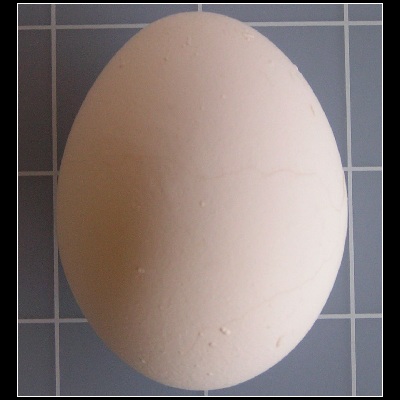
Picture image of a chicken egg used for example here(egg_42_in_ACAD.dwg )
One fine morning, I took 4 chicken eggs out of the refrigerator and boiled slowly and carefully
not to break the outer shell. Then later, after they are cooled down,I took photos of these eggs.
Author's Note:
The only reason I boiled the egg specimen is that I might break the shell and make a mess
on the table. I did not want to waste food. Another method I have tried is open a small hole
on the side and drain the content on the container for later cooking usage. After cleaning
the inside by water , let it dry for at least a few hours. Then insert the perforated material using
spray can. The advantage of this approach is that sample specimen can be archived for a long time
and by using a nail on the board, it can be easily fixed in the desired position for taking photos.
I tried to place the object in such manner that the axis of symmetry is horizontal to the table,
and aligned as closely as possible to the reference line on the table.
Notes: A few tips for taking egg's image.
Use a large size metal hex nut beneath an egg to maintain the imaginary axis of rotational symmetry
horizontal. Sharp metal edge and rough egg's surface give enough friction to make a delicate
adjustment.
It is better to take photos in the sunroom during daytime to avoid sharp shadows.
The grid spacing on the background vinyl mat is one inch. So the size of the egg
is about 2.5 inches long and 2 inches wide.
Since digital phote image is in JPG file format, it can be easily imported to ACAD.
The picture above is one of the well focused images.
It is easy to see that in spite of my efforts, the egg's axis of symmetry is slightly off to the left .
So the first task is to define the axis of symmetry (Y-axis) based on the imported image.
The author made the following assumption regarding the radii of
the egg's upper & lower ends.
(1) "The centers of the arcs of the upper and lower ends are on
the axis of symmetry (and revolution)."
(2) "The radii of the circles of both ends are local minimum"
--Step 2 --Use CAD to digitize the egg shape
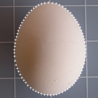
*********** egg_42_digitized.dwg ***********
After importing the image file to AutoCAD, create enough number of points to form
a smooth curve along the egg's boundary line. Use zoom and Pan commands.
The result is shown above.
Next step is finding the axis of symmetry.
There are 2 different approaches to find the axis of symmetry.
(1) Use the interesting property that the distance of the axis of symmetry is the minimum
length
connecting points on the top and bottom.
(2) Find the evolute circles on the top and bottom and the line connecting the centers of the circles
is the axis of symmetry.
First approach
We use the drawing file shown above.(egg_42_digitized.dwg)
After loading egg_draw.lsp, execute find_axis.
Executables for finding the symmetry axis:
Load egg_draw.lsp ---> (load "egg_draw")
To execute: from command line: find_axis
The author selected 10 points around the top area, and 8 points near the bottom area.
What the program do is compute distance between these two groups of points,and find the
line of maximum length and shows it in red color.
The process is shown in the next animation.
See Symmetry axis finding in animation.
Use browser's "Back" button to come back to this page.
If you do not have AutoCAD, but other CAD which can display this dwg file,
then you draw several lines and compare their length.
The longest line is the symmetric line to be sought after.

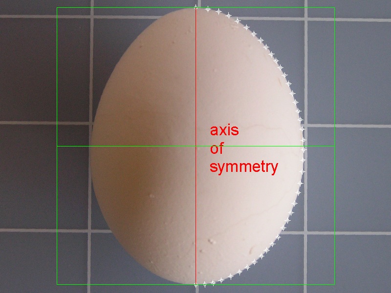
***************************** egg_42_axis.dwg ****************************
Now we can see that the top of the digitized egg is slightly tilted to the left and
the length of the symmetric line must be set to unit value.
This can be accomplished using "ALIGN" command in AutoCAD as follows:
The points onn the top and bottm are moved to points (0,1) amd (0,0), respectively.
This operation will adjust the height of the egg to a unit value.(normalized !)
From now on the points on the left hand side are not necessary, so these points are erased.
A unit square (1 X 1)(in green color) is added to the drawing.
The modified result is shown below.
***************************** egg_42_base.dwg ****************************
Second approach
This approach is the comibination of finding the axis of symmetry and the circle radii for the top
and the bottom, because the centers of evolute circles on both ends are on the axis of symmetry
and the line connecting these two centers forms the axis of symmetry.
And it was not a simple task for the author to automate the process
writing
a program. So the author does not recommend this approach, but this is a good example of
how
the "CIRCLE"'s 3-point option can be used to locate the evolute line.
First , create a polyline using the digitized points in the area near the top end.
After this operation, it is advisable to erase the digitized points.
Then divide this polyline into ,say, 20 equal parts.
Use these points to locate the circle using 3P option.
These 2 operations,Divide and 3-Point circle commands, are combined into 1 executable
named "EVOLUTE". This is included in egg_draw.lsp routine.
Do the similar operation for the bottom portion.
The result is shown in the drawing shown below.
********** egg_42_top_end_3.dwg *********
*********** egg_42_normalized_1.dwg **********
--Step 2 --Find evolute points for the top and bottom
Let us start with egg_42_base.dwg .
(1) Create a POLYLINE using the digitized points starting from the top and
ending at the bottom.
The author defined LAYER4 as current layer and assigned color BLUE.
This will create POLYLINE in blue color. After this operation I erased
digitized points for clarity.
(2) Divide the blue POLYLINE into 24 equal pieces.
(3) Use MIRROR command to mirror a few points from the right to the left.
(4) Use CIRCLE command with 3-POINT option to define top and bottom circles.
Use 3 points each on the top and bottom.
The result is shown below. Layer of egg's image is set to HIDDEN.
****************************** egg_top_bot.dwg *******************************
--Step 3 --Find evolute point for the maximum radius
Start with the drawing above.(egg_top_bot.dwg)
(1) Use the executable "EVOLUTE" in egg_draw.lsp.
Select the blue PLOYLINE
Divide the line into 10 pieces.
Select the top and bottom points as starting and ending points.
The result is shown below. This is our 11 points egg.
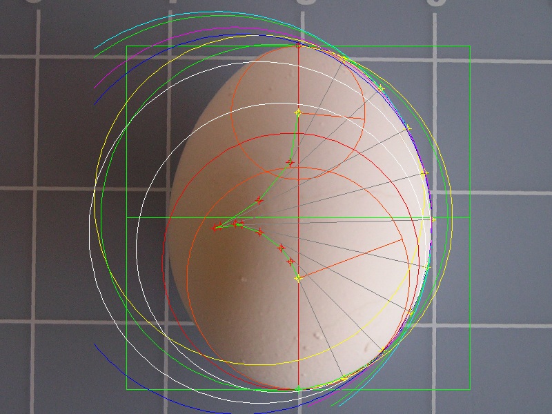
****************************** egg_evolute.dwg *******************************
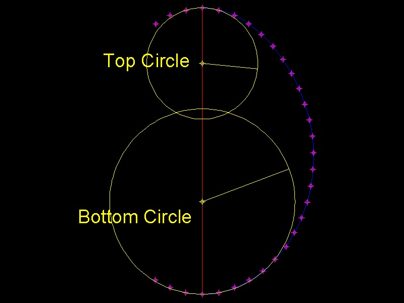
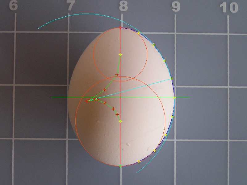
After a few editing, leaving only three circles(top, bot, and maximum radii),
our digital egg looks like this.
Orange color circle with yellow colored centers are for top and bottom circles
and the circle with the maximum radius is shown in CYAN color.
Evolute curve ,connecting orange colored points, is shown in green color.
************************* egg_evolute_top_bot_max.dwg **************************
After more editing, eliminating radius lines, we have the following result.
Now we have top and bottom circles, and circle with maximum radius .
The next step is find two circles connecting these 3 circles.
************************* egg_3_arcs.dwg **************************
--Step 4 --Find evolute points usig radical axis
The concept of "Radical Axis" is used to find the circle which connects two circles smoothly.It is explained in the previous section, but it is explained briefly here.
Radial Axis: (a) Definition
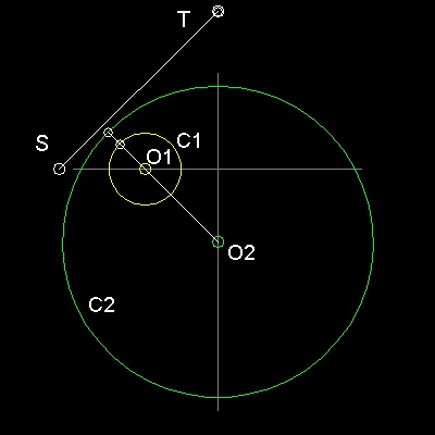
************radical_axis_1.dwg ************
Analytically equations of two circles equations are written as:
     Circle C1 : C (X,Y) =  X2 + Y2+ 2gX  + 2fY + c =0
     Circle C2 : C'(X,Y) =  X2 + Y2+ 2g'X + 2f'Y+ c'=0
Then C(X,Y) - C'(X,Y) = 0
is called the "Radical Axis" of the Circle C1 and C2,
and its line equation is written as follows:
2(g - g')X + 2(f - f')Y + c - c' = 0
or this can be written as x/ Xo + y/Yo = 1
The coordinate of the points this line intersects X & Y axis are
Xo = -(1/2)(c-c')/(g-g') , Yo = -(1/2)(c-c')/(f-f')
They are shown as points S and T in the drawing. The line segment ST
is the locus of points from which the tangents to both circles have
the same length !! This property can be used to find connecting circle
in the following way.
Radial Axis: (b) How to use it
Important properties of "Radical Axis":1. Line ST is normal to line O1O2.
2. The length of tangent lines drawn from a point on line ST are the same for Circles C1 and C2.
This last property can be used to find an evolute and its associated circle to fill the gap
between circles C1 and C2.
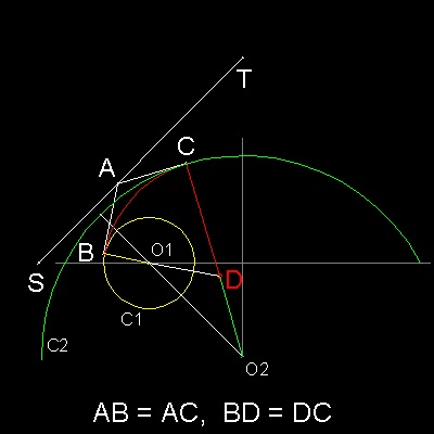
************radical_axis_3.dwg ************
B, C are the end points of tangent lines from A to circle C1 & C2.
Connect point C and O2.
The intersection of line CO2 and the extension of line BO1 is point D.
Since ST is a radical axis, AB = AC,
and both angles ABD & ACD are 90 degrees, BD = CD.
Therefore if point D is selected as
an evolute between O1 and O2,
we have a smooth continuous curve made up of 3 arcs.
First arc :center at O1, and starts from x-axis to point B.
Second arc:center at D, starts from B and ends at C.
Third arc :center at O2,starts at C to the point symmetric to point C wrt Y-axis.
Radial Axis: (c) Find the radical axis easy way
If the reader has an access to AutoCAD, just use the excutable "Radical_Axis"in egg_draw.lsp. Simply select 2 circles, top and middle(max radius), and then bottom and middle.
Two line segements are drawn as follows.
If the reader does not have AutoCAD,then he/she can still find the line using compass and
ruler,according to the graphical method explained in the previous section.
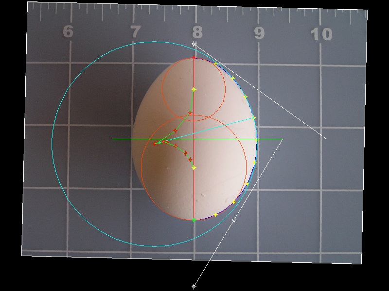
**************************** egg_radical_axis.dwg *****************************
Next step is to find the center of the connecting circles.
(1) select a point on the radical axis.
(2) Draw two lines tangent to two circles.
(3) Points A & P are selected on the radical axes.
Points B,C, Q & R are the end of tangent lines.
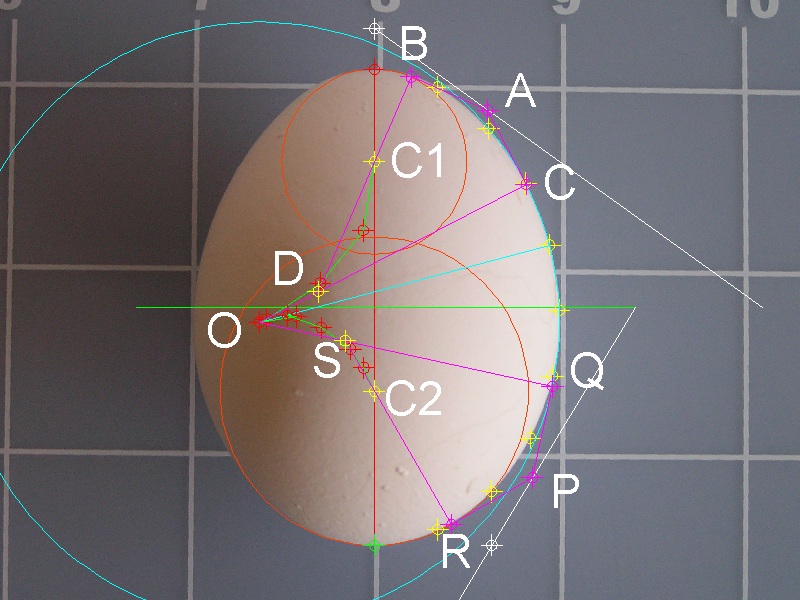
*************************** egg_connect_circles.dwg ****************************
(4)Draw lines BC1, CO, RC2, & QO.
(5)Extend line BC1. This intersects line CO at point D.
(6)Extend line RC2. This intersects line QO at point S.
(7) Points D & S are the center of the connecting circles
and their radii are CD , QS , respectively.
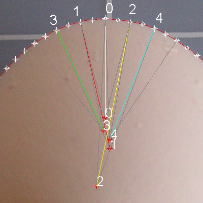
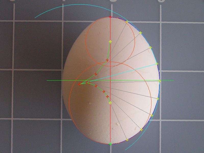
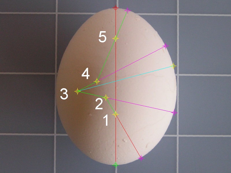
The evolute curve made up of 5 points look as follows:
Points 1 through 5 are the centers of the arcs.

**************************** egg_42_5pt.dwg *****************************
--Step 5 --Draw arcs using 5 evolute points
The final resulting evolute is made up of the following five points.
1 X= 0.000000 Y= 0.323543
2 X=-0.061299 Y= 0.429494
3 X=-0.241728 Y= 0.469124
4 X=-0.117993 Y= 0.532991
5 X= 0.000000 Y= 0.805787
**************************** egg_42_5pt_evol.dwg *****************************
Using these 5points, it is possible to draw arcs.
But if you have an access to AutoCAD, you can use the executable "EVOL_5PT"
in egg_draw.lsp .
See Final 5 pt evolute drawing in animation.
Use browser's "Back" button to come back to this page.
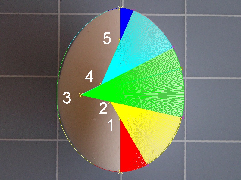
**************************** egg_42_5pt_evol_final.dwg *****************************
Here is another trial solution.
1 X= 0.000000 Y= 0.297796
2 X=-0.129099 Y= 0.475979
3 X=-0.212274 Y= 0.475997
4 X=-0.169188 Y= 0.501581
5 X= 0.000000 Y= 0.750981
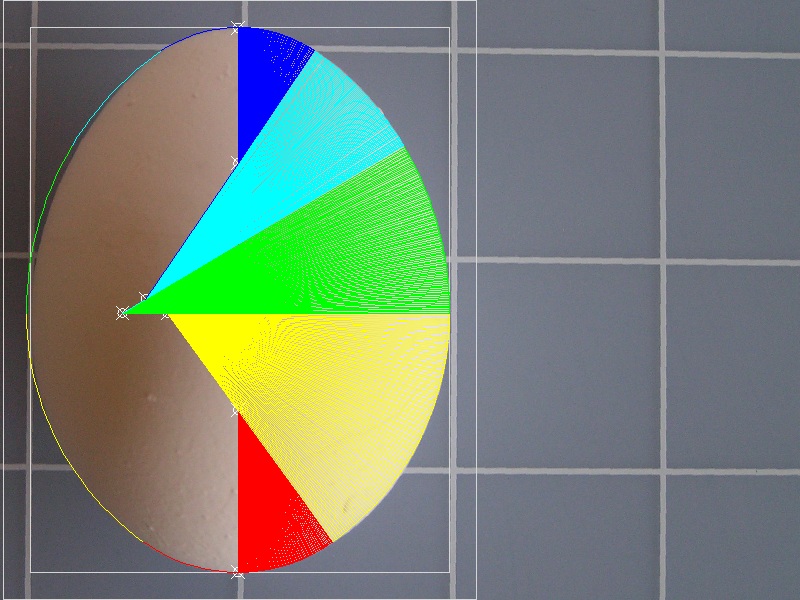
**************************** egg_42_end.dwg *****************************
After all these efforts, the author feels that two more points are
required to have a good match up . But that will left for the readers with challenging spirits.
Points data can be modified in the program and you can draw any variation of curves.